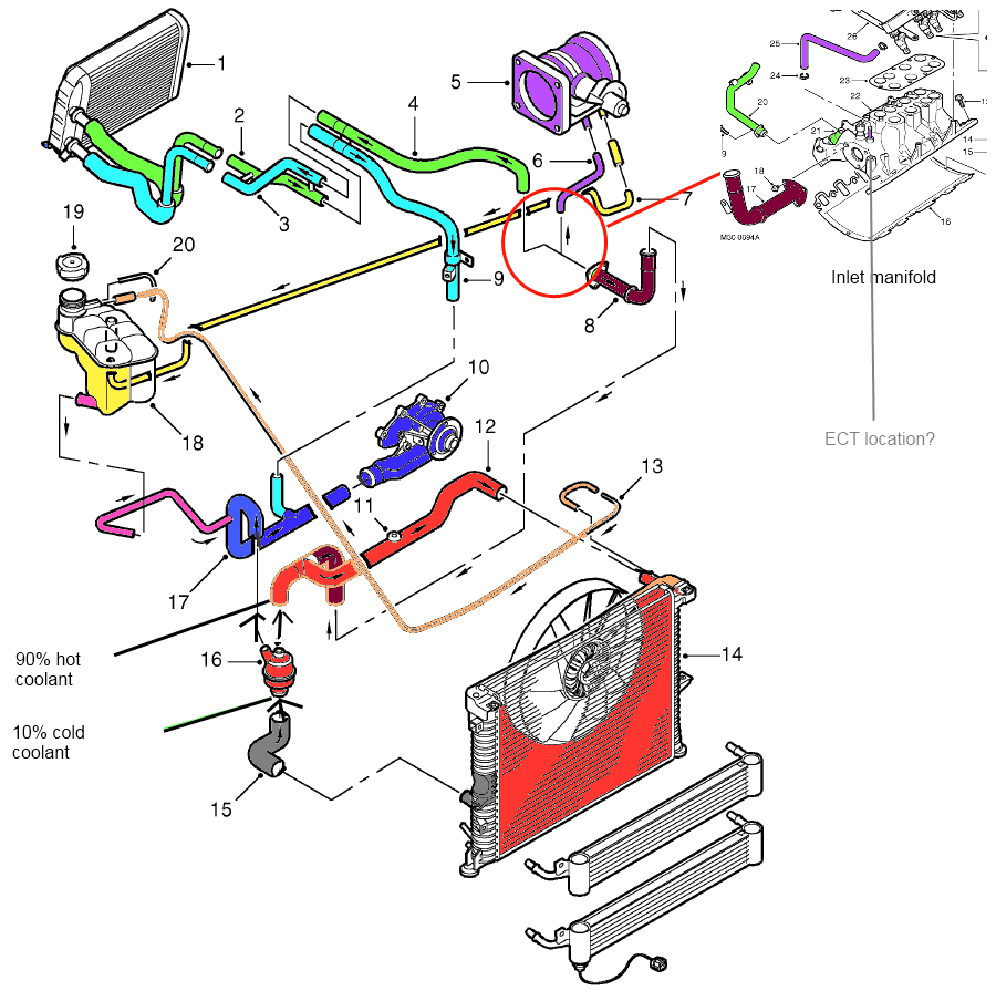
2004 Ford 6 0 Engine Cooling System Diagram

Visual Guide To Cooling System Parts Diagram For 2004 Ford 6 Page 44 • add motorcraft premium gold engine coolant (yellow colored), vc 7–a (u.s., except ca and or), vc 7–b (ca and or only), meeting ford specification wss m97b51–a1. note: use of motorcraft cooling system stop leak pellets, vc 6, may darken the color of motorcraft premium gold engine coolant from yellow to golden tan. The 6.0 powerstroke coolant flow diagram is a great tool to use when troubleshooting cooling system problems. it can help you locate leaks, identify blockages, and determine if there is enough coolant flowing through the system. the 6.0 powerstroke coolant flow diagram is a great way to see how the coolant flows through your engine.

Ford 6 0 Cooling System Diagram 2.0 cooling system basics fig. 2.1 reference: 6.0 power stroke 2003.25 “f” series super duty features descriptions unique service procedures and general diagnostics the diagram above shows the 3 circuits that the engine coolant takes from the water pump. there is a circuit for each side of the engine and one to the oil cooler egr cooler. Page 20: water pump. reservoir reservoir object. injector sleeve • the 6.0l power stroke uses stainless steel injector sleeves to seal coolant from the injector and to transfer heat from the injector to the coolant. • the injector sleeve is replaceable. see unique service procedures or service manual for more details. Here is a direct link to the cooling system flow chart. page 17: cooling system. thanks alot! 6.0l power stroke diesel coolant flow diagram i need to flush out my block and heater core as part of my rebuild resulting from a blown oil cooler. i know i have seen a diagram for the coolant flow on this site before but i cant seem to find it now. 6.0 powerstroke bible. reply like. chrisski. 4934 posts · joined 2014. #8 · may 22, 2019. the premade solution for what i think you're looking for is bpd remote oil cooler, or ipr makes the same version. then you take the ipr coolant filter and install it before the coolant in for the oil filter.

6 0 Powerstroke Coolant Flow Diagram Here is a direct link to the cooling system flow chart. page 17: cooling system. thanks alot! 6.0l power stroke diesel coolant flow diagram i need to flush out my block and heater core as part of my rebuild resulting from a blown oil cooler. i know i have seen a diagram for the coolant flow on this site before but i cant seem to find it now. 6.0 powerstroke bible. reply like. chrisski. 4934 posts · joined 2014. #8 · may 22, 2019. the premade solution for what i think you're looking for is bpd remote oil cooler, or ipr makes the same version. then you take the ipr coolant filter and install it before the coolant in for the oil filter. 6 piston cooling tubes. 8. high pressure hydraulic pump oil reservoir. • this reservoir (below oil cooler) has a constant supply of oil for the pressure hydraulic oil pump. it has an approximate capacity of 0.9 l (0.95 qt). 303 01c 11 engine — 6.0l diesel 303 01c 11 description and operation (continued) 2005 f 250, 350, 450, 550 super duty. Ford escape 2020 2024 service manual: removal and installation exhaust gas recirculation (egr) cooler inlet tube. removal note: removal steps in this procedure may contain installation details. remove the fasteners. remove the egr cooler inlet tube, remove and discard the gaskets. installation clean and inspect the gasket surface and the studs.

Comments are closed.