2004 Jeep Grand Cherokee Wiring

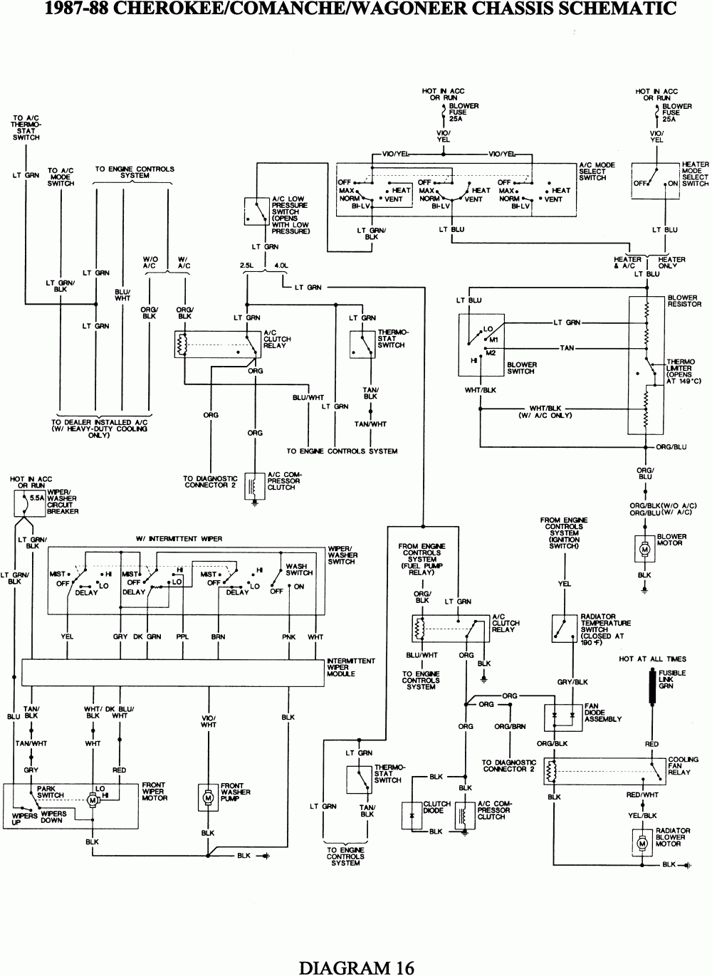
Wiring Diagram 2004 Jeep Grand Cherokee This article will provide you with a detailed overview of the 2004 jeep grand cherokee wiring diagram, including the location of the main fuse box, the various circuits that are controlled by the fuse box, and the color coded wires that are used in the vehicle's electrical system. the main fuse box for the 2004 jeep grand cherokee is located. Welcome to the jeepspecs in depth page on wj generation jeep grand cherokee wiring diagrams and pinouts. we have organized as much information as we could find into a helpful article below. is something incorrect or missing? please get in touch with us and we’ll fix it! radio connectors 1999 2001 (2x 7 pin) 2002 2004 (22 pin 10 pin) base radio (without cd changer & pci connectors.

2004 Jeep Grand Cherokee Wiring Schematic The wiring schematic can provide detailed diagrams of the wiring system in the 2004 jeep grand cherokee, making it easy to identify the exact wire you're looking for. the 2004 jeep grand cherokee wiring schematic is a valuable resource for both mechanics and diyers. it can save time and money by providing an accurate picture of the vehicle's. This video will show you how to access the complete jeep grand cherokee wiring diagrams and details of the wiring harness. diagrams for the following systems. The 2004 jeep grand cherokee wiring diagram will have the following components: battery cable – represents the positive terminal connection. ignition switch – connects to the starter motor. fuse box – connects to the battery, providing power to various systems. emission system – connects to important components such as the engine computer. Wiring diagrams – wiring diagrams are comprehensive visual depictions of the various wiring components of the 2004 jeep grand cherokee. these diagrams often show the color codes and routing of the wires, making it easier to install aftermarket parts and make modifications. grounding diagrams – grounding diagrams are used to help verify the.

Comments are closed.