3 Phase Automatic Changeover Switch With Circuit Diagram Y

3 Phase Automatic Changeover Switch With Circuit Diagram Y Wiring 120v & 240, 1 phase manual transfer switch – nec. the following wiring diagram in fig 3 shows the reliance manual transfer switch connected to the main 120 240 v panel and a portable generator. step by step guide is posted before in the post under the title wiring a portable generator using manual transfer switch for 120 & 240v. This video is explained about three phase automatic transfer switch (ats). this is used as a automatic changeover switch.if you have any questions, please co.

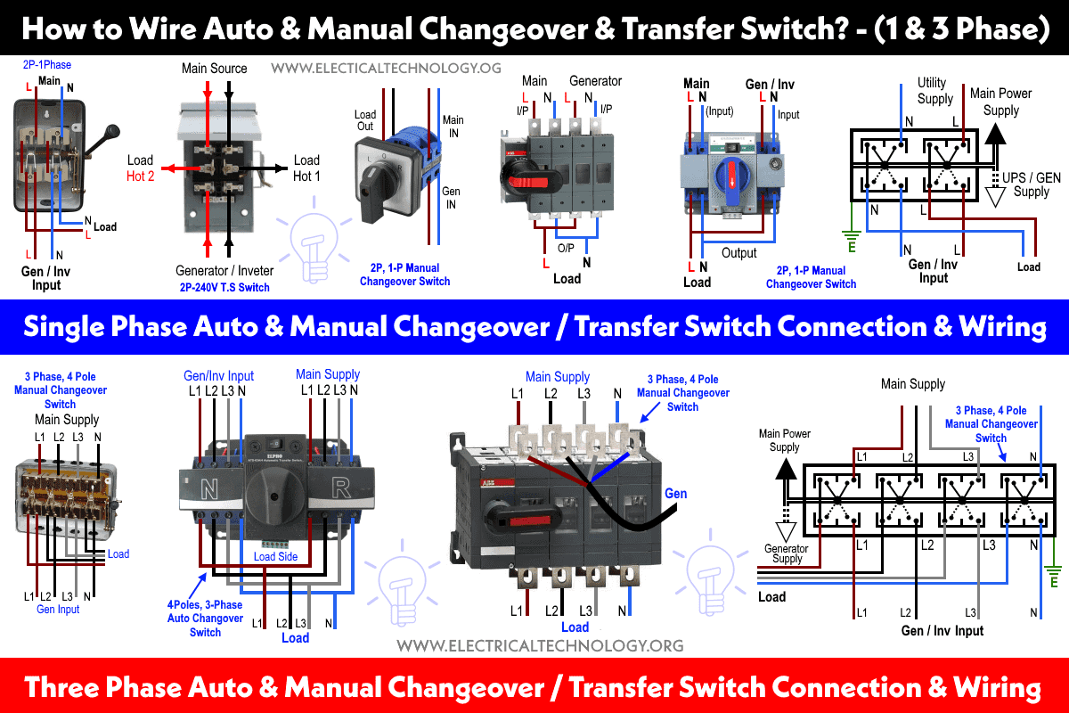
3 Phase Automatic Changeover Switch Circuit Diagram Pdf Connect the main power supply and the backup power supply (generator) to the input terminals of the changeover switch (related circuit breakers and contactors) as shown in the wiring diagram. ensure proper grounding and connection for protection. 5. connect load. connect the 3 phase load (e.g. distribution board, load center, three phase. Full practical wiring. step by step procedure on how to wire a 3 phase automatic changeover switch.please click the link below to watch the part 1 yo. When one or more phases are disconnected, the switch will be in the off position. this is how the device works to protect against power outages and load shedding. the wiring diagram for a three phase switch consists of three four wire circuits, each of which contains two neutral wires. the three circuits are connected to the main power supply. Let us understand the automatic 3phase change over switch in this informative diy tutorial, we delve into the intricacies of constructing an automatic 3 phas.

3 Phase Automatic Changeover Switch Circuit Diagram Pdf When one or more phases are disconnected, the switch will be in the off position. this is how the device works to protect against power outages and load shedding. the wiring diagram for a three phase switch consists of three four wire circuits, each of which contains two neutral wires. the three circuits are connected to the main power supply. Let us understand the automatic 3phase change over switch in this informative diy tutorial, we delve into the intricacies of constructing an automatic 3 phas. 3. familiarize yourself with the switch’s wiring diagram: it is essential to refer to the wiring diagram provided with the changeover switch. this diagram will show the various terminals and connections that need to be made. understanding the diagram beforehand will ensure a smoother and more accurate wiring process. 4. Use electrical cables to connect the line input of the switch to the utility power supply. ensure that the connections are secure and use wire connectors to join the cables together. 4. connect the backup power source. next, connect the backup power source, such as a generator, to the automatic changeover switch.

Comments are closed.