3 Phase Magnetic Contactor Wiring Diagram

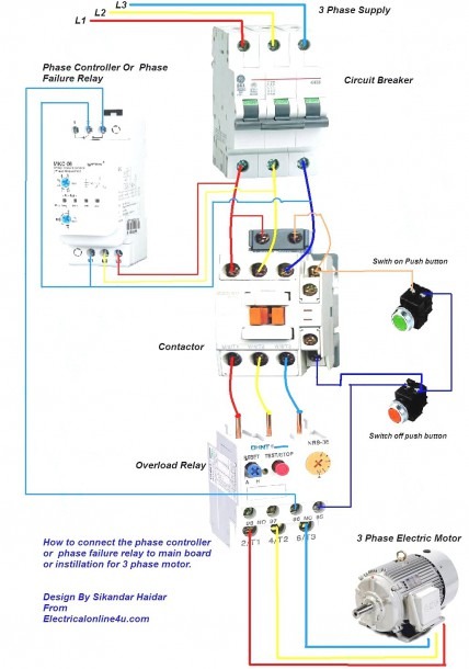
Magnetic Contactor Wiring Diagram Three Phase The wiring diagram of a magnetic contactor for three phase systems typically includes various components, such as the power supply lines, control circuit, thermal overload relay, and motor. the power supply lines deliver the three phase ac voltage to the contactor, while the control circuit consists of the start and stop buttons or switches. A 3 phase contactor is an electrical device used to control and switch three phase motors or other three phase loads. it is an essential component in industrial and commercial electrical systems, ensuring efficient and safe operation of machinery and equipment. the wiring of a 3 phase contactor involves connecting it to the power supply and the.

Magnetic Contactor Wiring Diagram Three Phase The 3 phase motor contactor is an essential component in motor control systems as it provides a safe and reliable method of controlling the power supply. it helps to protect the motor from overload, short circuits, and other electrical faults. it also allows for remote control and automation of motor operations. First, we will start with the main wiring power wiring. the three phase supply shown in the diagram, l1, l2, l3 which is connected to the mccb circuit breaker, and after that the supply goes to the magnetic contactor and from the contactor, the supply goes to the thermal overload relay, and from the thermal overload relay, the supply goes to 3 phase motor. A typical wiring diagram for a three phase contactor includes the main power supply, control circuit, and load connections. the main power supply connections are made to the contactor’s l1, l2, and l3 terminals. these terminals are typically labeled with the corresponding phase colors (e.g., l1 for phase 1). Wiring diagrams, sometimes called “main” or “construc tion” diagrams, show the actual connection points for the wires to the components and terminals of the controller. they show the relative location of the components. they can be used as a guide when wiring the controller. figure 1 is a typical wiring diagram for a three phase mag.

3 Phase Magnetic Contactor Wiring Diagram A typical wiring diagram for a three phase contactor includes the main power supply, control circuit, and load connections. the main power supply connections are made to the contactor’s l1, l2, and l3 terminals. these terminals are typically labeled with the corresponding phase colors (e.g., l1 for phase 1). Wiring diagrams, sometimes called “main” or “construc tion” diagrams, show the actual connection points for the wires to the components and terminals of the controller. they show the relative location of the components. they can be used as a guide when wiring the controller. figure 1 is a typical wiring diagram for a three phase mag. This diagram shows the internal components and wiring connections of a typical 3 phase contactor. at the heart of a 3 phase contactor is an electromagnet which is activated by a control coil. when the coil is energized, it creates a magnetic field that pulls down the main contacts, allowing the current to flow to the load. The first step to wiring a magnetic contactor for a three phase motor is to identify the three power lines that will be connected. these are typically labeled l1, l2, and l3 on the contactor. the contactor must then be wired so that the power from each of these lines can be switched on and off independently. this is done by connecting each line.

How To Wire A 3 Phase Contactor This diagram shows the internal components and wiring connections of a typical 3 phase contactor. at the heart of a 3 phase contactor is an electromagnet which is activated by a control coil. when the coil is energized, it creates a magnetic field that pulls down the main contacts, allowing the current to flow to the load. The first step to wiring a magnetic contactor for a three phase motor is to identify the three power lines that will be connected. these are typically labeled l1, l2, and l3 on the contactor. the contactor must then be wired so that the power from each of these lines can be switched on and off independently. this is done by connecting each line.

Magnetic Contactor Wiring Diagram Three Phase

Comments are closed.