3 Wire Coolant Temperature Sensor Wiring Diagram Asmaaakasha

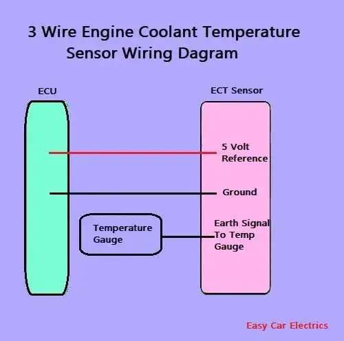
1 2 3 Wire Coolant Temperature Sensor Wiring Diagram 3 wire coolant temperature sensor wiring diagram. the two wires, a “5 volt reference”, and a “ground wire” go to the ecu, and the third wire “earth 1 wire for temp gauge” goes to the cluster mounted temperature gauge by providing an earth link to the temperature gauge. in three wire coolant temp sensors, the ecu does not control the. The wiring diagram for a 3 wire coolant level sensor typically includes three distinct wires: power, ground, and signal wire. the power wire supplies the sensor with electrical power, allowing it to function properly. the ground wire acts as a return path for the electrical current, completing the circuit. the signal wire is responsible for.

3 Wire Coolant Temperature Sensor Wiring Diagram Asmaaakasha Hummertech: thanks, that diagram was exactly what i was looking for! bill ford: 3 wire ect sensor pn 12551708 and connector pn 12102748. 1993 gmc yukon 2dr 4x4, 6.0l 4l80e swap, wheatley tune, 3 inch magnaflow true duals, 6.5 inch dick cepek stage 1 lift, 35's, 4.56 gears, front posi lok. reply with quote. A 3 wire pt100 wiring diagram is a diagram that illustrates how to properly connect a pt100 temperature sensor with three wires. pt100 is a type of resistance temperature detector (rtd) that is widely used in industrial applications to measure temperature accurately. it is designed to have a resistance of 100 ohms at 0 degrees celsius. The wiring diagram consists of several components which are connected to your car’s electrical system by wires. the sensor’s output signal is sent to a gauge or a warning light, where it is measured and monitored. the gauge or warning light is then activated if there is a problem with the cooling system. it is also useful to know the type. How to test coolant temp sensor wiring brilliant guide. ect 2 installation. 2008 saturn astra coolant temp wiring. techdoc. i have a 2002 ford f350 7 3l and the coolant temp e on dash flickers up down all time as its doing. temperature sensor wiring lead color code engine. gsic global service information center. p0117 p0118. two wire temp.

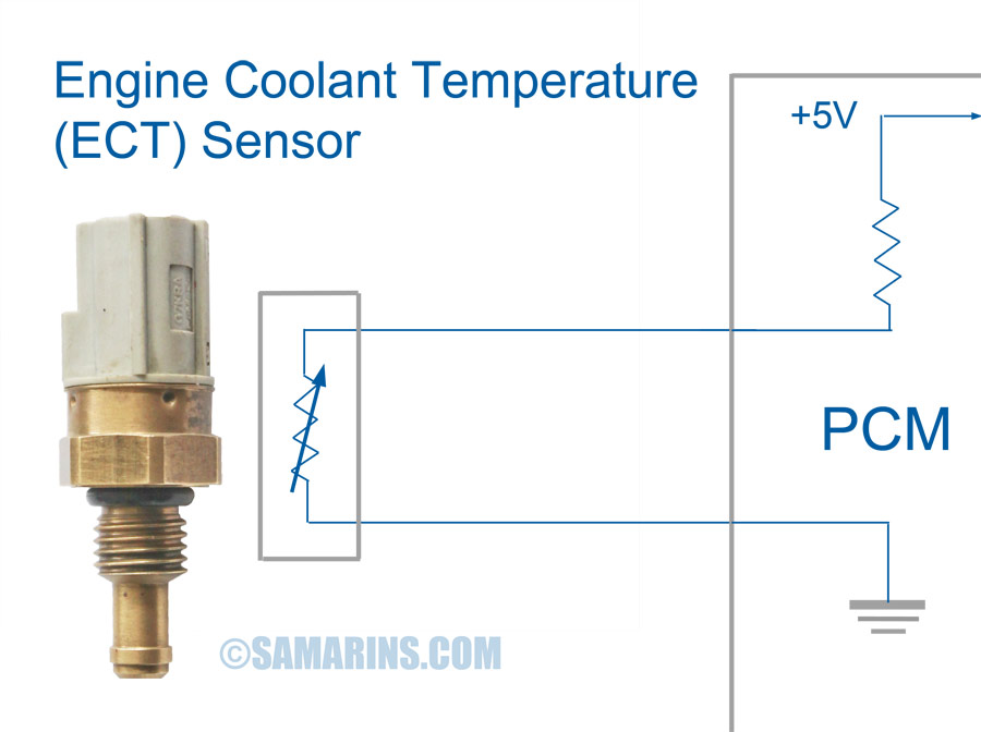
3 Wire Coolant Temperature Sensor Wiring Diagram Knittysta The wiring diagram consists of several components which are connected to your car’s electrical system by wires. the sensor’s output signal is sent to a gauge or a warning light, where it is measured and monitored. the gauge or warning light is then activated if there is a problem with the cooling system. it is also useful to know the type. How to test coolant temp sensor wiring brilliant guide. ect 2 installation. 2008 saturn astra coolant temp wiring. techdoc. i have a 2002 ford f350 7 3l and the coolant temp e on dash flickers up down all time as its doing. temperature sensor wiring lead color code engine. gsic global service information center. p0117 p0118. two wire temp. A mat sensor is installed & measures the intake plenum or an intake runner temperature. an iat sensor is installed & measures the air intake tube temperature. it's the same sensor that can be used two different ways. the mat & iat sensor perform the same task in terms of aftermarket efi systems. A 3 wire coolant temperature sensor wiring diagram is based on the fact that a coolant temperature sensor is a variable resistor. in its most basic form, the coolant temperature sensor has three wires – one that is connected to the battery positive terminal, one that is connected to the ground wire and one that is connected to the engine.

1 2 3 Wire Coolant Temperature Sensor Wiring Diagram A mat sensor is installed & measures the intake plenum or an intake runner temperature. an iat sensor is installed & measures the air intake tube temperature. it's the same sensor that can be used two different ways. the mat & iat sensor perform the same task in terms of aftermarket efi systems. A 3 wire coolant temperature sensor wiring diagram is based on the fact that a coolant temperature sensor is a variable resistor. in its most basic form, the coolant temperature sensor has three wires – one that is connected to the battery positive terminal, one that is connected to the ground wire and one that is connected to the engine.

Comments are closed.