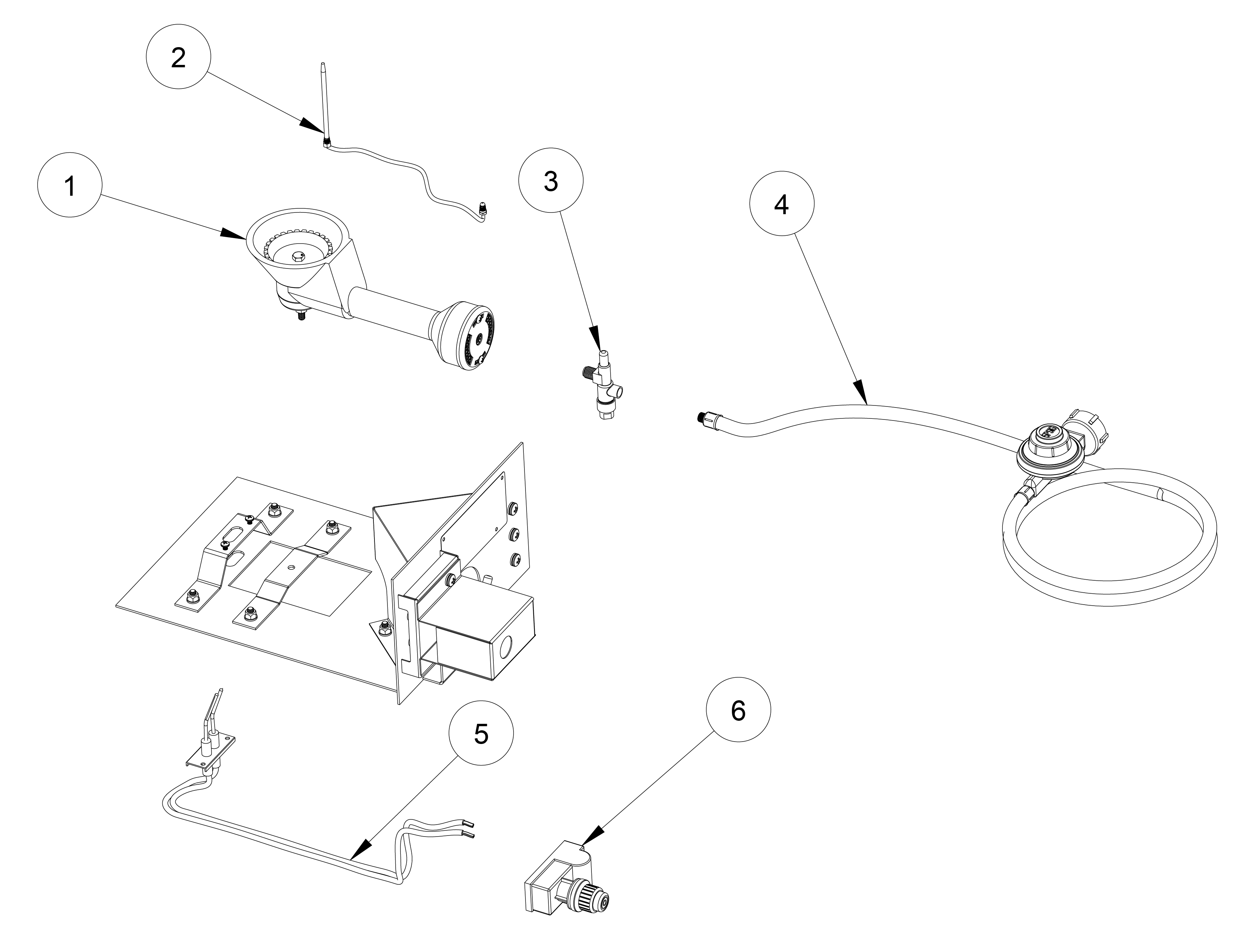
35 Propane Regulator Parts Diagram Diagram Resource

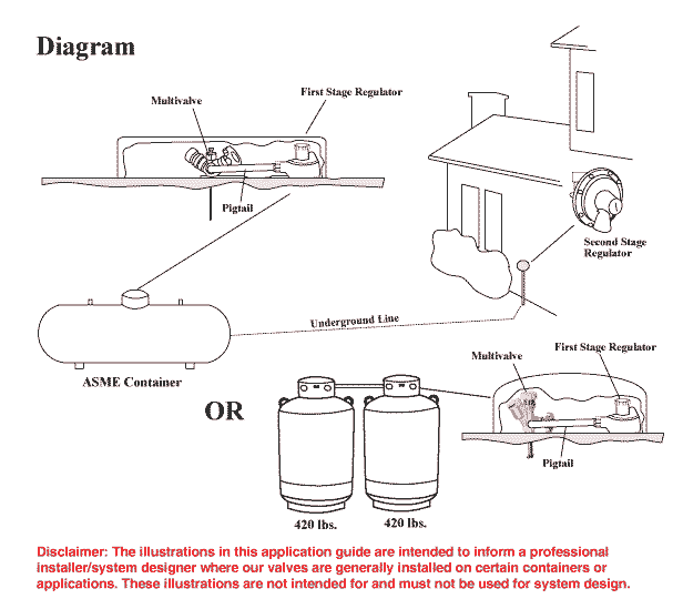
35 Propane Regulator Parts Diagram Diagram Resource Propane regulators are manufactured with pressure relief devices built inside the regulator body and operate in a similar manner as that of a tank pressure relief valve. if triggered, the relief valve will open and allow gas to escape through the regulator vent. the vent needs to remain unobstructed so that the gas may escape if necessary. Introduction to propane regulators. propane regulators are a critical component in your home’s heating equipment, ensuring the safe and efficient use of propane gas. they act as a safety barrier between the high pressure of the tank and the appliances you use in your home. understanding the function of a propane regulator.

35 Propane Regulator Parts Diagram Diagram Resource The model j regulator vaporizer delivers reliable performance and pressure output consistency. its relia bility, especially with questionable fuel quality, has made it an industry standard for many years. two vapor outlet pressures are available. the standard jb blue provides 1.5” w.c. (0.37 kpa). the op tional jo provides 0.5” w.c. (0.12. Diaphragm – senses pressure and starts and stops the flow of gas vapor. main spring – provides tension on the diaphragm to regulate flow. relief – if excess pressure flow beyond the capacity of the regulator occurs, the relief mechanism (spring) allows the propane vapor to exit through the relief valve. this prevents excess pressure from. Installing a propane regulator near a source of heat is not only extremely unsafe, it is illegal. regulators should be installed so that they are protected from sources of extreme heat. regulator diaphragms are made of synthetic material and or rubber and while they are designed to withstand certain amounts of heat, regulator diaphragms are not. These figures appear on the regulator dial as percentages spanning from 5 to 95. to get the exact amount of propane in the tank, simply convert it into gallons. for instance, if your 500 gallon tank shows it is at the 60% mark, the tank is currently holding 300 gallons. that is 0.6 x 500=300 gallons.

35 Propane Regulator Parts Diagram Diagram Resource Installing a propane regulator near a source of heat is not only extremely unsafe, it is illegal. regulators should be installed so that they are protected from sources of extreme heat. regulator diaphragms are made of synthetic material and or rubber and while they are designed to withstand certain amounts of heat, regulator diaphragms are not. These figures appear on the regulator dial as percentages spanning from 5 to 95. to get the exact amount of propane in the tank, simply convert it into gallons. for instance, if your 500 gallon tank shows it is at the 60% mark, the tank is currently holding 300 gallons. that is 0.6 x 500=300 gallons. Feb 25, 2020. propane regulators have always played a key role within propane systems in terms of safety, as explained a few weeks ago in an article in lp gas magazine by randy warner, product safety manager for cavagna group north america. “the purpose of the regulator is to control the flow of gas vapor from the container to the burner tip. The main parts of a propane tank include: 1. tank valve: located at the top of the tank, the tank valve is used to control the flow of propane. it has a protective cap and is typically equipped with a pressure relief valve for safety. 2. fill valve: the fill valve is where propane is delivered into the tank.

Comments are closed.