4 Pin Cb Mic Wiring

4 Pin Cb Mic Wiring Find out how to wire different types of microphones for your cb radio, such as 4 pin, 5 pin, or 6 pin. see the pin end views, color codes, and wiring diagrams for various brands and models of radios and mics. 1 844 925 2688. m f 10am to 5pm cst. 🕘. store hours. m f 9am 6pm. sat 9am 5pm. sun closed. free repair your cb microphone yourself with these mike wiring diagrams. get cb microphone help here, at walcott radio.

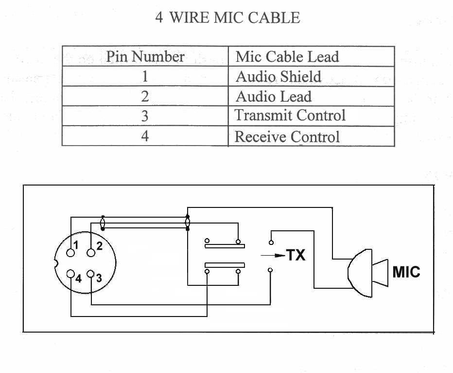
Cb Mic Wiring Guide The remaining two wires, commonly white and blue, are responsible for transmitting audio signals. here’s a breakdown of the typical wiring connections in a cobra cb mic: pin 1 (shield wire): connect this wire to the cb radio’s common ground. pin 2 (audio output): connect this wire to the cb radio’s audio input or microphone input. The cobra 29 4 pin cb mic wiring diagram is an essential tool for anyone looking to properly connect their microphone to the cobra 29 cb radio. this diagram provides a clear and detailed illustration of the different wires and connections involved in the setup, ensuring that users can easily understand and follow the correct wiring procedure. Learn how to wire a cb microphone for optimal performance and communication. find out the different types of connectors, wires, and pins, and how to match them with your cb radio. Step 2: prepare the cb radio. locate the microphone input jack on your cb radio. it is usually labeled as “mic” or “mic in”. identify the corresponding pins for the transmit, receive, ground, and common wires. refer to the cobra 4 pin mic wiring diagram for accurate pin assignments. step 3: connect the wires.

Cobra 4 Pin Cb Mic Wiring Diagram Learn how to wire a cb microphone for optimal performance and communication. find out the different types of connectors, wires, and pins, and how to match them with your cb radio. Step 2: prepare the cb radio. locate the microphone input jack on your cb radio. it is usually labeled as “mic” or “mic in”. identify the corresponding pins for the transmit, receive, ground, and common wires. refer to the cobra 4 pin mic wiring diagram for accurate pin assignments. step 3: connect the wires. Cb mic wiring diagram. the diagram below shows the proper wiring connection of 4 wired mic cable. a certain wire has an appropriate pin number that is necessary to be followed. not following the details will cause your household harm. 4 pin plug pinout. microphone wiring for the 4 pin (u) uniden microphone wiring. diagrams below are viewed from solder side of plug.

Comments are closed.