4 Speaker Wiring Diagram Wiring Flow Line
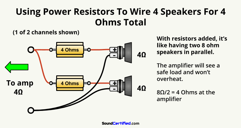
4 Speaker Wiring Diagram Wiring Flow Line The recommended speaker impedance ratings are usually listed above the speaker wire posts. a home stereo, for example, may often list 6 16 ohms as being ok for use. also, attempting to wire two 8 ohm speakers in parallel to an 8 ohm stereo would have the same effect. (two 8 ohm speakers in parallel is equal to 4 ohms total that the amp will see). 2. familiarize yourself with the connector pins. a speakon connector typically has four pins, with the top two pins used for the positive and negative signals, and the bottom two pins used for the twist lock mechanism. take the time to understand the pin configuration to ensure proper wiring. 3.

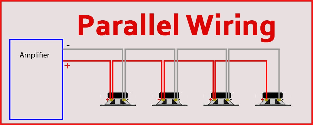
How To Wire A 4 Channel Amp To 4 Speakers And A Sub A Detailed Guide Here is a basic guide for wiring four speakers in parallel, assuming each speaker has an impedance of 8 ohms: connect the positive terminal of the amplifier to the positive terminal of the first speaker. connect the negative terminal of the amplifier to the negative terminal of the first speaker. To calculate the total impedance of speakers wired in parallel, you would divide the product of the individual impedance values by the sum of those values. so, if you have four 4 ohm speakers wired in parallel, the total impedance would be (4 x 4 x 4 x 4) (4 4 4 4) = 4 ohms. it is important to note that when wiring speakers of different. The series wiring diagram helps to understand the specific arrangement and connection of the speakers. in a series circuit, the positive terminal of one speaker is connected to the negative terminal of the next speaker, creating a continuous flow of electrical current. this means that the total impedance, or resistance, of the speakers is. All in all, you should have a comprehensive understanding of how speakers work and how to connect them to an amplifier using four post terminals now. there are 3 ways to wire speakers with 4 terminals and they are as follows: 1. leaving the conductive bar between the terminals and connecting one set of wires 2. bi wiring 3.

Diagram Of Series Wiring 4 Speakers The series wiring diagram helps to understand the specific arrangement and connection of the speakers. in a series circuit, the positive terminal of one speaker is connected to the negative terminal of the next speaker, creating a continuous flow of electrical current. this means that the total impedance, or resistance, of the speakers is. All in all, you should have a comprehensive understanding of how speakers work and how to connect them to an amplifier using four post terminals now. there are 3 ways to wire speakers with 4 terminals and they are as follows: 1. leaving the conductive bar between the terminals and connecting one set of wires 2. bi wiring 3. A speakon connector typically has 2, 4, or 8 pins, each carrying an audio signal. these pins are designated as positive ( 1), negative ( 1), and the remaining pins are used for additional channels or features. the wiring diagram of a speakon connector shows the specific pin assignments and their functions, ensuring the correct signal flow and. One common wiring configuration for the 4 pin xlr connector is the standard balanced configuration. in this configuration, the pins are wired as follows: pin 1: ground (gnd) – this pin is used for the ground connection. pin 2: positive ( ) – this pin carries the positive phase of the audio signal.

The Speaker Wiring Diagram And Connection Guide The Basics You Need To A speakon connector typically has 2, 4, or 8 pins, each carrying an audio signal. these pins are designated as positive ( 1), negative ( 1), and the remaining pins are used for additional channels or features. the wiring diagram of a speakon connector shows the specific pin assignments and their functions, ensuring the correct signal flow and. One common wiring configuration for the 4 pin xlr connector is the standard balanced configuration. in this configuration, the pins are wired as follows: pin 1: ground (gnd) – this pin is used for the ground connection. pin 2: positive ( ) – this pin carries the positive phase of the audio signal.

4 Speaker Wiring Diagram Greenist

Comments are closed.