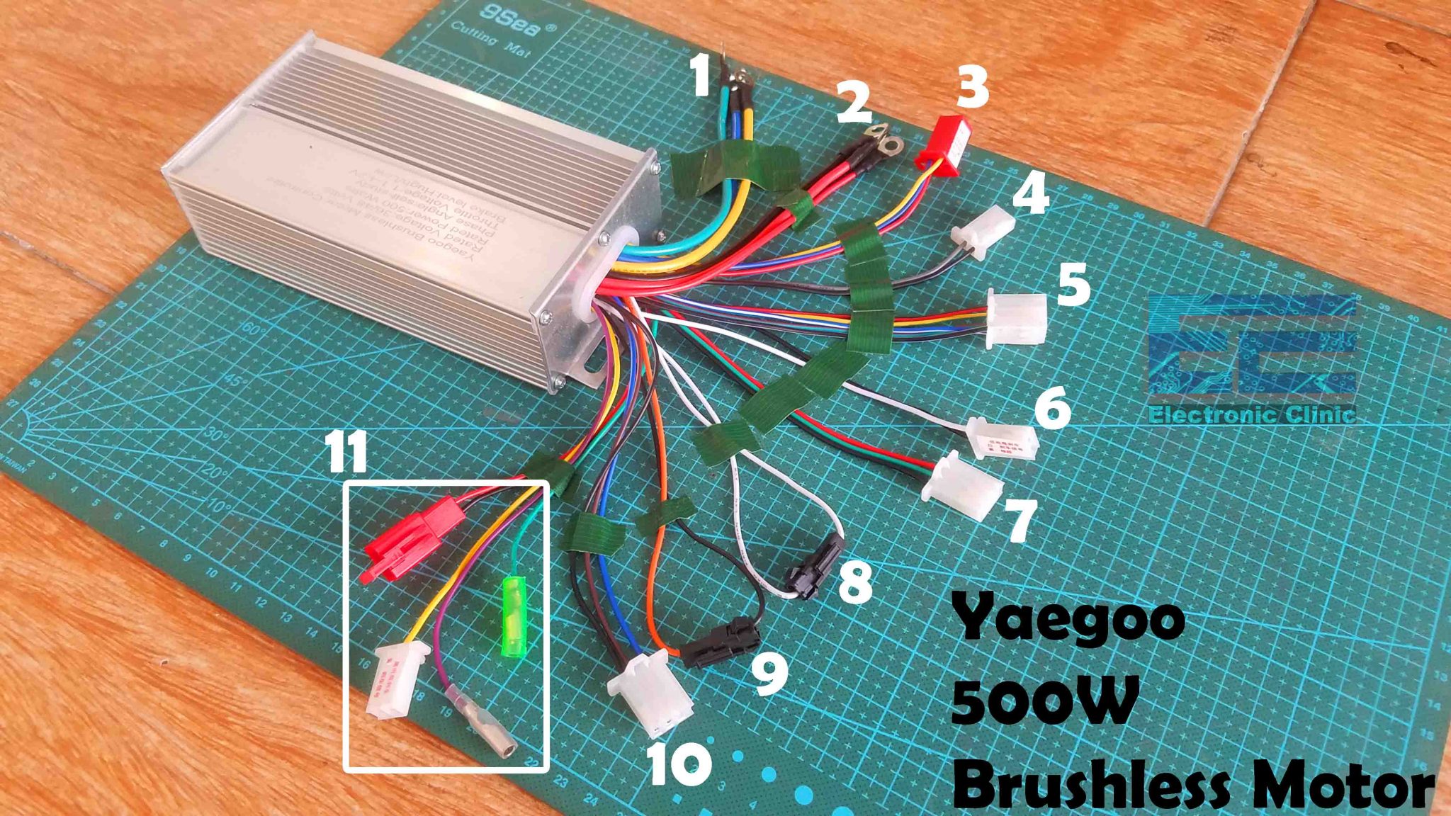
500w Brushless Dc Motor Controller Review Wiring

500w Brushless Dc Motor Controller Review Wiring Youtube The wiring diagram for a brushless motor controller shows the connections between the various components. it typically includes the input and output terminals, power connections, sensor connections, and control signal connections. understanding this diagram is crucial for proper installation and troubleshooting of the controller. About press copyright contact us creators advertise developers terms privacy policy & safety how works test new features nfl sunday ticket press copyright.

500w Ebike Brushless Motor Controller Wiring Explanation Hoverboard Connecting a brushless dc motor (bldc) to a 3 phase sensor & sensorless bldc controllers. this video shows the phase and hall sensor wiring connection of a. The rated voltage is 36 to 48 volts. the rated power is 500 watts with phase angle self study and the throttle voltage is from 1.1 to 4.2 volts. so, with this ebike brushless motor controller you can control almost all types of bldc motors which are up to 500 watts and 36 to 48 volts. motor three phases green, blue, and yellow. The three phase power connector to the motor. the hall sensor connector to the motor. the throttle cable connector. self learning wires. other connectors have extra functions you might or might not need and it's not necessary to connect those. this is a normal brushless dc controller that we can get in market. each connector marked with functions. The wiring diagram of a brushless dc motor controller outlines these components and how they are connected. when wiring a brushless dc motor controller, there are a few key aspects to consider. first, you must make sure the power supply is connected to the correct voltage. for example, if you are using a 24 volts supply, you must use a 24 volts.

500w Ebike Brushless Motor Controller Wiring Explanation Hoverboard The three phase power connector to the motor. the hall sensor connector to the motor. the throttle cable connector. self learning wires. other connectors have extra functions you might or might not need and it's not necessary to connect those. this is a normal brushless dc controller that we can get in market. each connector marked with functions. The wiring diagram of a brushless dc motor controller outlines these components and how they are connected. when wiring a brushless dc motor controller, there are a few key aspects to consider. first, you must make sure the power supply is connected to the correct voltage. for example, if you are using a 24 volts supply, you must use a 24 volts. A bldc motor controller regulates the speed and torque of the motor; it can also start, stop, and reverse its rotation. to understand the working principles of the controller, let us start first with the construction of a brushless motor. its major components comprise: an armature or rotor made of permanent and in many cases neodymium magnets. The diagram will be explained in detail, and the components of the controller will be identified. the wiring diagram for a 36v brushless motor controller is shown below. the controller is connected to the battery pack through the red and black wires. the positive battery terminal is connected to the " " terminal on the controller, and the.

Comments are closed.