700r4 Tcc Wiring Diagram For Your Needs
700r4 Tcc Wiring Diagram For Your Needs Tweet. #1. 700r4 tcc lockup wiring. september 4, 2011, 12:09 pm. here is a diagram from tci i believe: here is a diagram and a picture (several pics collaged together)of what found when i dropped my trans pan: normally, i believe that pin a is 12 volts, and pin d is ground. is this still the case in my situation, based on the diagram of my. Remove the wires from the clips and unplug the wiring harness from the connector near the detent roller spring. pry connector tab away from the plug and pull the plug down. do not pull on the wires. step 3 based on your application, find the wiring diagram to determine the proper fourth gear pressure switch location.

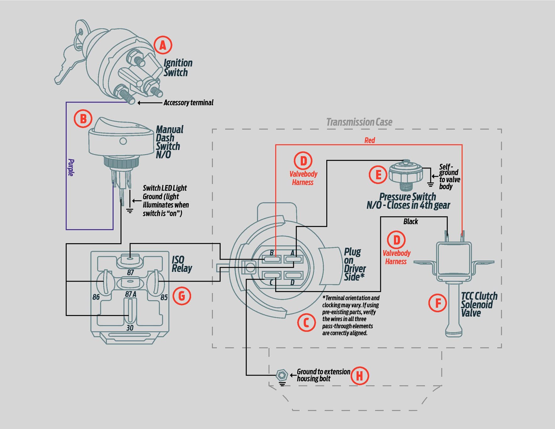
700r4 Tcc Wiring Question to you is: that diagram next to connector, does it represent what is in the tranny, if so then i think you only need switched 12v at the purple (420) terminal. reasoning is that the internals might have those switches to make sure that you are in 4th gear for the lockup to happen. Step 2: locate the transmission connector. next, locate the transmission connector on the driver’s side of the transmission. this connector is typically round or square in shape and contains several pins. referencing your wiring diagram, identify the correct pins that correspond to the torque converter lockup system. Real world wiring diagram the fuse holders connect to the vehicles fuse block. follow these easy steps. 1. fuse holder connects to the lighted manual switch's bottom terminal providing the 12v power source. see (a) 2. the center terminal of the switch is connected to the wire that leads down to the oil pressure switch on trans case. see (b) 3. The purple wire is power from the gauge fuse then through the brake pedal switch. in the 1988 light truck wiring manual it shows the purple wire connecting to the rwal module and going through a 510 ohm .5 watt resistor between the rwal module and the brake pedal switch. the power for the tcc does not go through the resistor.

700r4 Tcc Wiring Real world wiring diagram the fuse holders connect to the vehicles fuse block. follow these easy steps. 1. fuse holder connects to the lighted manual switch's bottom terminal providing the 12v power source. see (a) 2. the center terminal of the switch is connected to the wire that leads down to the oil pressure switch on trans case. see (b) 3. The purple wire is power from the gauge fuse then through the brake pedal switch. in the 1988 light truck wiring manual it shows the purple wire connecting to the rwal module and going through a 510 ohm .5 watt resistor between the rwal module and the brake pedal switch. the power for the tcc does not go through the resistor. See all 27 photos. the 700 r4's 2,500 rpm stall converter wouldn't lock up, resulting in excessively high rpm and reduced mileage at freeway speeds. although the rod was spirited around town. There are 2 styles of solenoids used in the 700r4. first is a 1 wire self grounding unit that only requires positive (12v) feed to it. the other is a 2 wire unit that requires a ground and a positive feed. either 1 or 2 wire will work but changes what pressure switch is required. there are 4 different pressure switches used in 700r4s & there.

700r4 Tcc Wiring Diagram See all 27 photos. the 700 r4's 2,500 rpm stall converter wouldn't lock up, resulting in excessively high rpm and reduced mileage at freeway speeds. although the rod was spirited around town. There are 2 styles of solenoids used in the 700r4. first is a 1 wire self grounding unit that only requires positive (12v) feed to it. the other is a 2 wire unit that requires a ground and a positive feed. either 1 or 2 wire will work but changes what pressure switch is required. there are 4 different pressure switches used in 700r4s & there.

700r4 Tcc Wiring Diagram For Your Needs

Comments are closed.