Ac Condenser Wiring Diagram Wiring Diagram

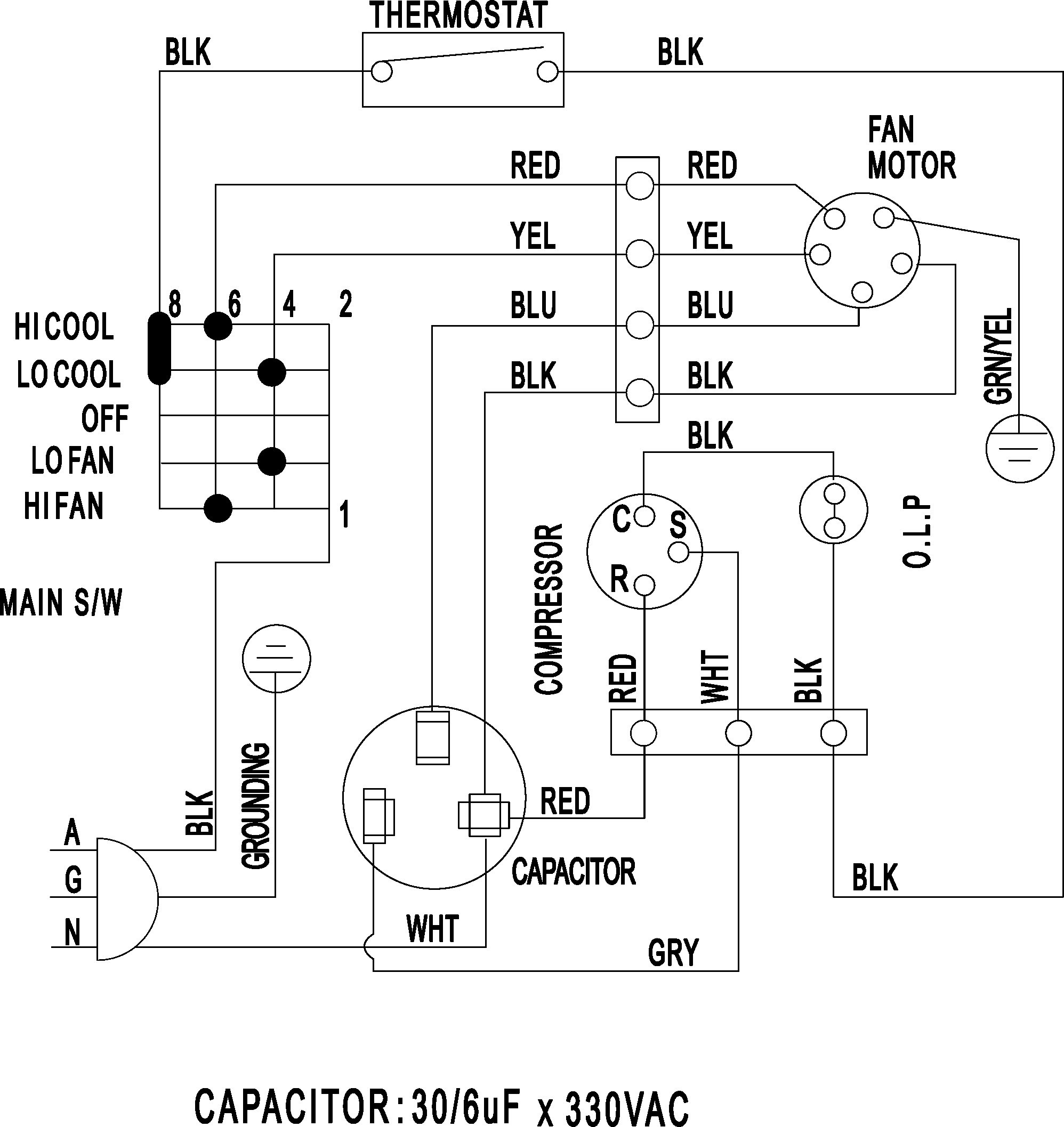
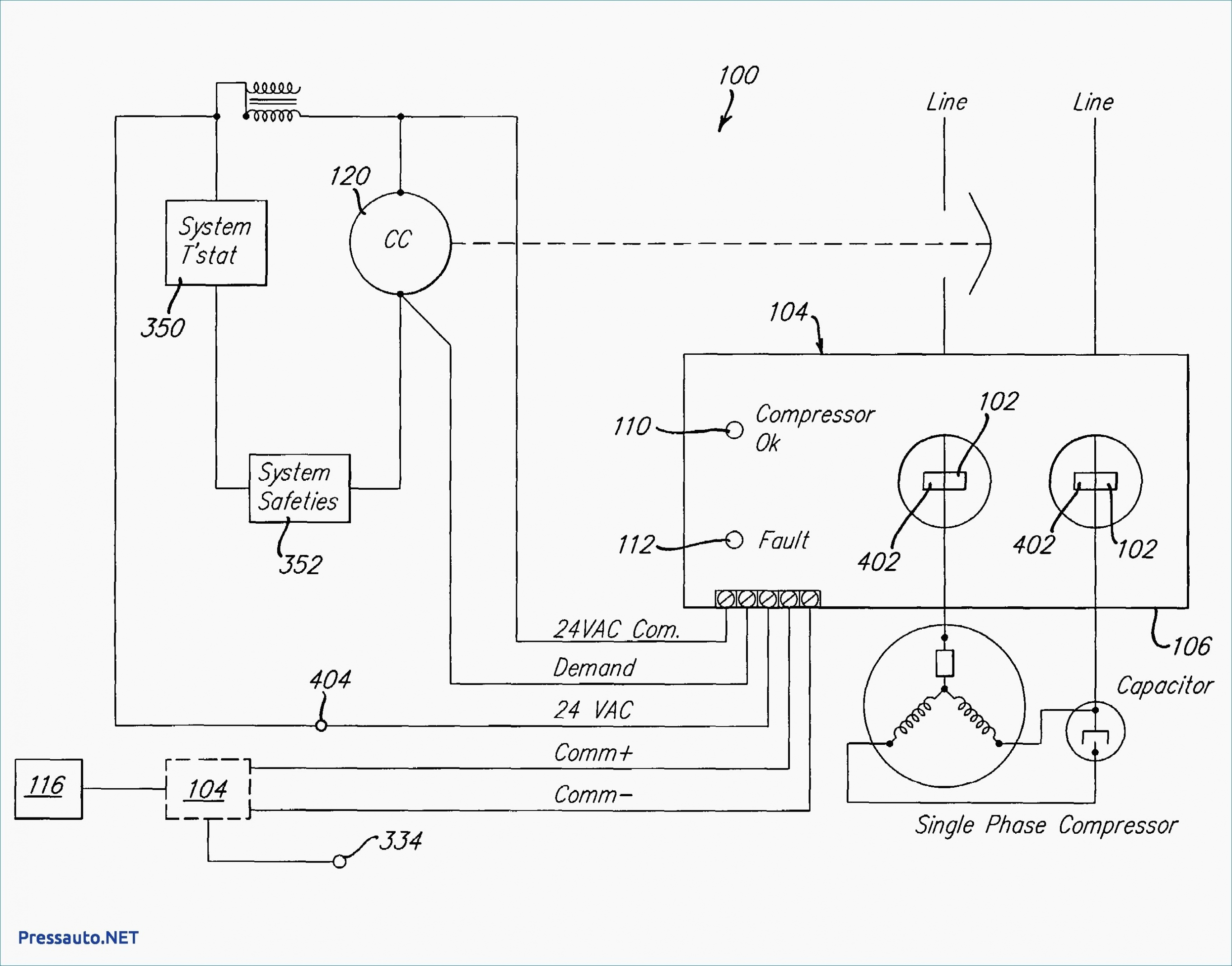
Wiring Diagram A C Condenser Parts An ac condenser wire diagram is a visual representation of the wiring connections in an air conditioning condenser unit. the condenser unit is an essential component of any air conditioning system, as it helps to dissipate heat from the refrigerant and turn it back into a liquid state. the wire diagram provides a detailed overview of the. The wiring diagram for an air conditioner condenser typically includes several components, such as the compressor, fan motor, and capacitor. these components are connected in a specific way to ensure proper operation of the condenser unit. the wiring diagram provides a visual representation of how these components are wired together.

Ac Condenser Wiring Diagram Wiring Diagram The basic wiring diagram of an air conditioner consists of several components, including the compressor, condenser, fan motor, and thermostat. the compressor is responsible for compressing the refrigerant gas and transferring it to the condenser, where it is cooled and turned back into a liquid state. the fan motor helps circulate the air over. Start by connecting the power wires to the terminal block on the condenser unit. typically, the power wires will be color coded as black for hot, white for neutral, and green or bare copper for ground. connect these wires to the corresponding terminals as indicated in the wiring diagram. 5. connect the control wires. The wiring diagram for an hvac (heating, ventilation, and air conditioning) condenser is an important tool for understanding how the electrical components of the unit are connected. it provides a visual representation of the wiring connections and can be used by technicians for troubleshooting and installation purposes. In a three phase air conditioner, the condenser receives high pressure and high temperature refrigerant gas from the compressor and cools it down using a combination of air and water. once the gas is cooled, it condenses into a liquid and is ready to enter the evaporator. 3. expansion valve.

Ac Condenser Unit Wiring Diagram The wiring diagram for an hvac (heating, ventilation, and air conditioning) condenser is an important tool for understanding how the electrical components of the unit are connected. it provides a visual representation of the wiring connections and can be used by technicians for troubleshooting and installation purposes. In a three phase air conditioner, the condenser receives high pressure and high temperature refrigerant gas from the compressor and cools it down using a combination of air and water. once the gas is cooled, it condenses into a liquid and is ready to enter the evaporator. 3. expansion valve. Basic steps for wiring an air conditioner. run electrical cable from the service panel to an air conditioner disconnect switch near the a c unit and connect it to a new circuit breaker in the panel. turn the breaker off. prepare a length of cable to run from the disconnect switch to the a c unit’s control panel. The diagram typically includes information about the power supply, thermostat, compressor, fan motor, condenser, and evaporator. it shows how these components are connected and how the electrical current flows through the system. an air conditioner wiring diagram is an essential tool for anyone working on or installing an air conditioning system.

Comments are closed.