Aftermarket Cooling Fan Wiring Diagram

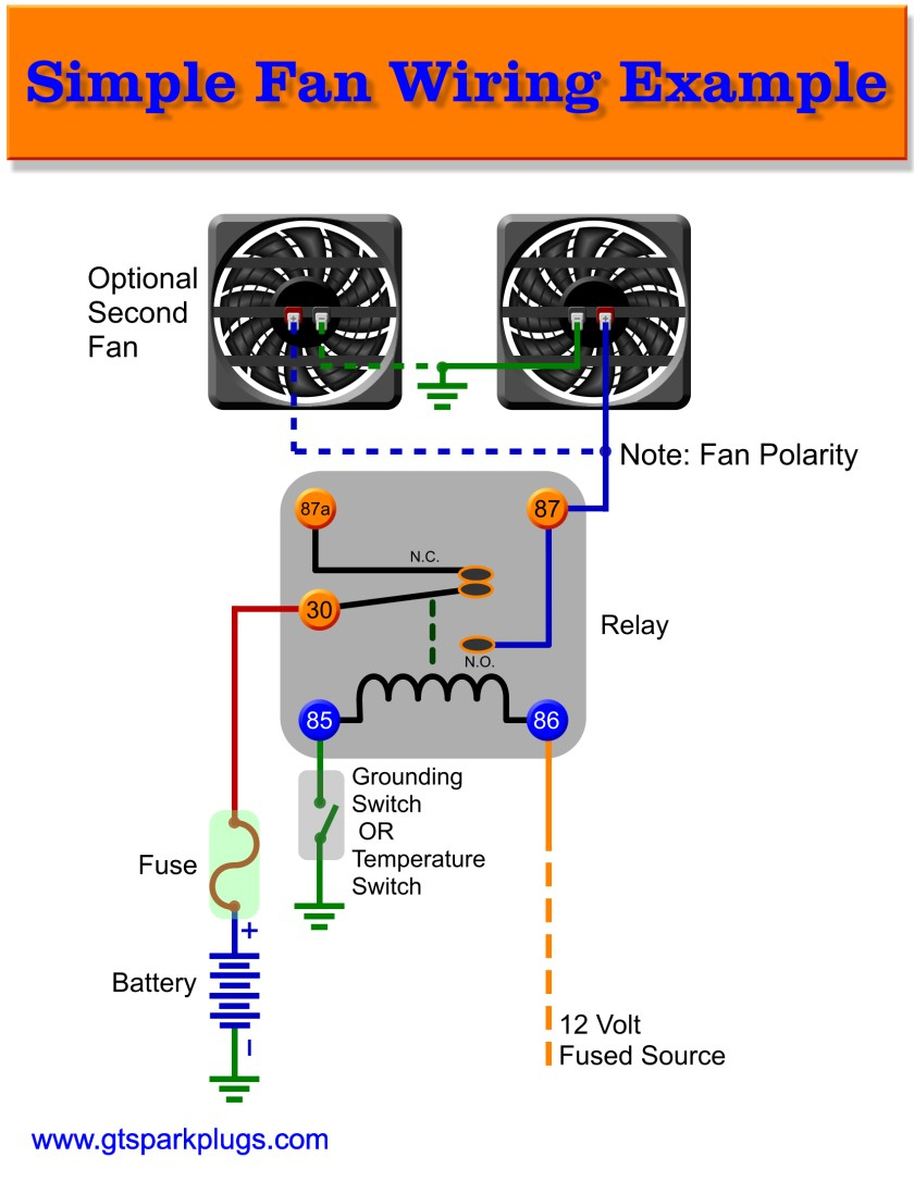
Aftermarket Electric Fan Wiring Diagram With dual cooling fans, there are two methods for wiring up the relay kit. this is based on the draw from the fans, if the fans are larger and draw more than 15 amps each, it's recommended to install a second relay kit as shown below. for smaller fans, both fans can be connected to a single relay as shown above, and the proper fuse should be. Start with taking both of the positive wires from the fans and connect them to the yellow wires on each relay. you will then need to run switched power (usually from your ignition switch, but modern replacement wiring harnesses usually have a fused fan relay trigger wire) to the blue wires on the relays. next, both of the black wires from the.

Aftermarket Electric Fan Wiring Diagram Start your wiring project by taking both of the positive wires from the fans and run them to the yellow wires on each relay (tab 87). then connect switched power (usually from your ignition switch), to the blue wires on both relays (tab 86). next, splice together both black wires from the relays (tab 85) and connect them to the thermostat. 87 (red wire) connects to the positive wire on the electric fan. 30 (other red wire) needs constant 12 volt power from the battery. 86 (gray white wire) goes to the ignition switch. This video shows how to easily wire an electric radiator fan circuit into any car. this fan wiring diagram includes a fan relay, a temperature switch, and a. Using a yellow butt connector and the supplied red wire, connect one end of the 10 ga. red wire to the fan #2 (remaining fan) positive ( ) wire. run the 10 ga. red wire connected to the fan #2 positive lead to the red wire (furthest from the adjustment screw). cut the wire to the appropriate length. connect wires using one of the supplied.

Radiator Cooling Fan Wiring Diagram This video shows how to easily wire an electric radiator fan circuit into any car. this fan wiring diagram includes a fan relay, a temperature switch, and a. Using a yellow butt connector and the supplied red wire, connect one end of the 10 ga. red wire to the fan #2 (remaining fan) positive ( ) wire. run the 10 ga. red wire connected to the fan #2 positive lead to the red wire (furthest from the adjustment screw). cut the wire to the appropriate length. connect wires using one of the supplied. How to wire electric radiator cooling fans using the alloy works relay and temperature switch kit. this kit can be purchased here: alloyworksplus. Crimp the ¼” spade connector terminal on to the grey wire and attach to the terminal on the thermoswitch. route and connect the purple 12 gauge wire to the printed to the positive ( ) wire extending from the electric fan motor. if you want to change direction of air reverse this connection. cut the red 10 gauge wire so that it terminates.

Aftermarket Cooling Fan Wiring Diagram вђ Tiketha How to wire electric radiator cooling fans using the alloy works relay and temperature switch kit. this kit can be purchased here: alloyworksplus. Crimp the ¼” spade connector terminal on to the grey wire and attach to the terminal on the thermoswitch. route and connect the purple 12 gauge wire to the printed to the positive ( ) wire extending from the electric fan motor. if you want to change direction of air reverse this connection. cut the red 10 gauge wire so that it terminates.

Comments are closed.