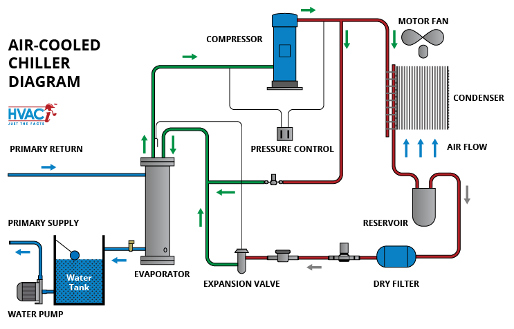
Air Cooled Chiller Plant Diagram

Air Cooled Chiller System Schematic Diagram A chilled water system can be separated into water cooled and air cooled. water cooled chilled water systems are larger and more efficient than air cooled chilled water systems. a typical water cooled chilled water system consists of 4 major components as below: chiller. cooling tower. This video guides you through the basic operation of a chiller, making use of animations, illustrations, 3d models and real world photographs to help build y.

Air Cooled Chiller Plant Diagram Chillers, p. 12 cooling towers, p. 22 coil selection, p. 32 unitrane® vertical high rise fan coil, p. 36 pumps, p. 38 hydronic system accessories, p. 50 pipe sizing, p. 52 control valves, p. 54 tracer® chiller plant control, p. 60 trane design assist™, p. 62 repeatable, simple yet flexible tracer® chiller plant controls provide. The chillers will produce “chilled water” which is pumped out around the building to the air handling units (ahu’s) and fan coil units (fcu’s) which remove the unwanted heat from the building and transfer it into the chilled water loop. the chilled water will enter the ahu’s fcu’s at around 6°c (42.8°f) and by the time it leaves. An air cooled chiller works by absorbing the heat from processed water. once the water in the air handler system is used, it becomes warm and is sent back to. The unwanted heat is removed from the condenser using fans which blow cooler ambient air across the condenser coil. in this example the fans will have total volume flow rate of 30.75 cubic meters per second (30,750 liters per second). the air temperature going in is around 30°celsius (86°f) and the temperature out will be around 44°c (111°f).

Comments are closed.