Allison Transmission Shift Selector Wiring Diagram

Allison Transmission Shift Selector Wiring Diagram Lly or overheat.checking fluid levelsuse the following proced. on.to enter the fluid level function:park the vehicle on a level surface, shift to n. neutral) and apply the parking brake.using a pushbutton shift selector, simultaneously. press the up and down arrows one time.for a bump lever shift selector,. 1. park the vehicle on a level surface, apply the parking brakes, and chock the tires. fig. 1. 4. if the fluid level is low, check the transmission for leaks, and correct as needed. 5. if needed, add eaton−approved fluid until it is motorhome series 3000 4000 rv tech library.

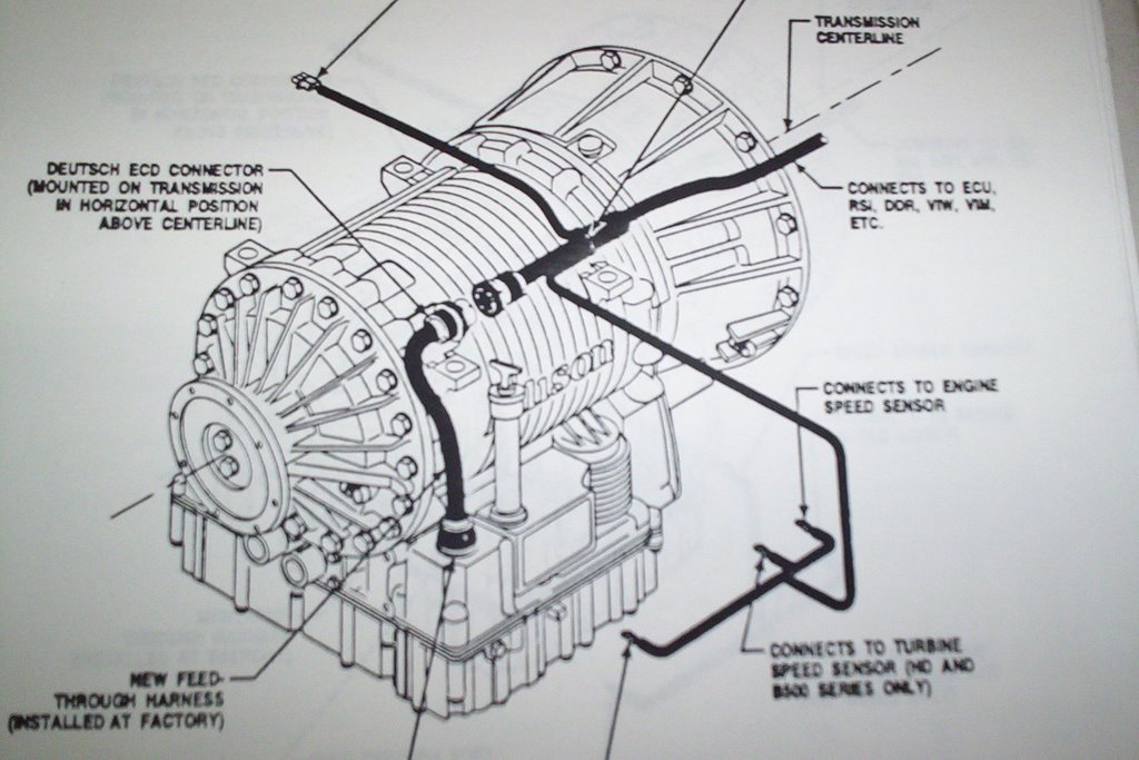
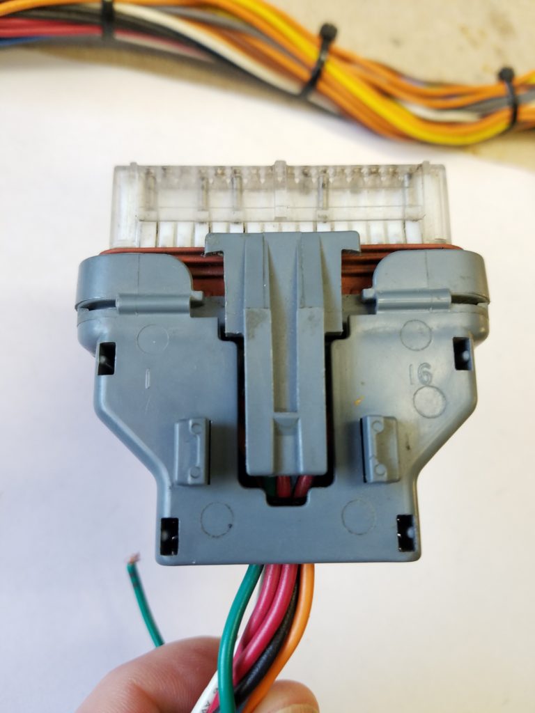
Allison Transmission Shift Selector Wiring Diagram The wiring diagram for an allison transmission shift selector is a visual representation of the electrical connections and components involved in the shifting process. it shows how the different parts of the system are interconnected and how they work together to control the shifting of the transmission. This brochure will help you understand shift selector readouts and enjoy long, trouble free operation of your allison automatic. shift selector models detailed information on oil levels, diagnostic codes and prognostic fea tures for your specific shift selector can be found on the following pages. if your vehicle has a shift selector that has a:. Filter life monitor. for either a pushbutton or bump lever shift selector, press and hold the mode button for approximately 10 seconds while in filter life monitor mode. or. for either a pushbutton or bump lever shift selector, perform the following shift sequence with the ignition on, but the engine off. Page 5: section 1 with prognostics with oil level sensor. 1 . park the vehicle on a level surface, shift to n (neutral) and apply the parking brake . 2 . using a pushbutton shift selector, simultaneously press the up and down arrows one time . for a bump lever shift selector, press the diagnostics button one time .

Allison Transmission Shift Selector Wiring Diagram Filter life monitor. for either a pushbutton or bump lever shift selector, press and hold the mode button for approximately 10 seconds while in filter life monitor mode. or. for either a pushbutton or bump lever shift selector, perform the following shift sequence with the ignition on, but the engine off. Page 5: section 1 with prognostics with oil level sensor. 1 . park the vehicle on a level surface, shift to n (neutral) and apply the parking brake . 2 . using a pushbutton shift selector, simultaneously press the up and down arrows one time . for a bump lever shift selector, press the diagnostics button one time . This document provides a wiring schematic for allison 3000 and 4000 product families. it includes a key for reading the diagram, abbreviations for colors, and a wiring diagram connecting sensors, transmission components, and connectors. the diagram labels signal names and pin locations for various connectors. Repair parts for the internal wiring harness and for wiring harness components attached to the shift selector will be available through the allison transmission parts distribution center (pdc). use the p n from your appropriate parts catalog or from appendix e in this manual. allison transmission is responsible for warranty on these parts. •.

Comments are closed.