Architectural Drawings Explained Ck

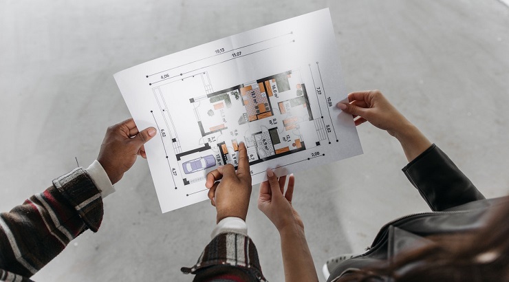
Architectural Drawings Explained Ck A 1 2″ scale is double the size of a 1 4″ scale. 3. plan details. in architectural drawings, plan details are large scale drawings that offer details on how construction will be undertaken. plan details are usually 3 4″ = 1′ 0″ or larger and they identify all the materials and connections for the construction project. 4. Know that you should never scale a drawing. if you cannot locate anything on the drawing with the dimensions given, get more dimensions from the architect. 2. understand the architectural sheets. these sheets will usually be numbered " a ", such as "a 001", or a1 x, a2 x, a3 x and so forth.

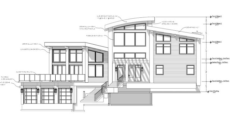
Share More Than 144 Building Elevation Sketch Super Hot In Eteachers The first principle is scale. scale refers to the ratio between the size of the drawing and the size of the actual object. it's crucial to maintain accurate scale in architectural drawings to ensure that the design can be correctly interpreted and built. another fundamental principle is perspective. There are five main types of construction drawings, including architectural, electrical, plumbing, and finishing drawings – each serving a specific purpose. 1. architectural drawing. this drawing, which has the particulars of the project, is labelled as the mother drawing of all the drawings used in the construction field. Plan, section, and elevation are different types of drawings used by architects to graphically represent a building design and construction. a plan drawing is a drawing on a horizontal plane showing a view from above. an elevation drawing is drawn on a vertical plane showing a vertical depiction. a section drawing is also a vertical depiction. Labelling a drawing and having the text on the drawing can clutter the information. make sure you keep the labels aligned and slightly away from the drawing to keep things clear. if you are using arrows, try to keep them all at the same angles. a good option is vertical, horizontal and 45 degree angle only if possible.

Ck House Full Scale Studio Diagram Architecture Architecture Plan, section, and elevation are different types of drawings used by architects to graphically represent a building design and construction. a plan drawing is a drawing on a horizontal plane showing a view from above. an elevation drawing is drawn on a vertical plane showing a vertical depiction. a section drawing is also a vertical depiction. Labelling a drawing and having the text on the drawing can clutter the information. make sure you keep the labels aligned and slightly away from the drawing to keep things clear. if you are using arrows, try to keep them all at the same angles. a good option is vertical, horizontal and 45 degree angle only if possible. The main use of the 45 degree rule is horizontal. this is a simple and straightforward method used mostly on planning drawings, and it’s very easy to calculate. from a birds eye view, as with planning drawings, simply note 45 degrees away from the window in question on either side and draw a line outwards. Definition and purpose. architectural drawings are technical representations of buildings and structures, created to communicate detailed information about design, dimensions, construction methods, and material specifications. they serve several critical functions, including:.

Architecture Floor Plans Symbols Ck The main use of the 45 degree rule is horizontal. this is a simple and straightforward method used mostly on planning drawings, and it’s very easy to calculate. from a birds eye view, as with planning drawings, simply note 45 degrees away from the window in question on either side and draw a line outwards. Definition and purpose. architectural drawings are technical representations of buildings and structures, created to communicate detailed information about design, dimensions, construction methods, and material specifications. they serve several critical functions, including:.
Architectural Drawings Explained Printable Templates

Comments are closed.