Basic Circuit Diagram For Electronics

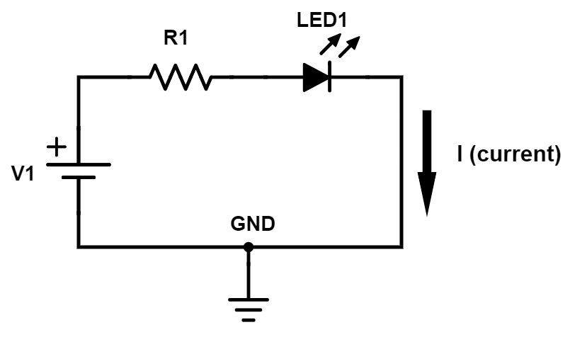
Circuit Diagrams Explained Circuit diagram connections. circuit diagrams or schematic diagrams show electrical connections of wires or conductors by using a node as shown in the image below. a node is simply a filled circle or dot. when three or more lines touch each other or cross each other and a node is placed at the intersection, this represents the lines or wires. That's all there is to schematic reading! knowing component symbols, following nets, and identifying common labels. understanding how a schematic works opens up the whole world of electronics to you! check out some of these tutorial, to practice your new found schematic knowledge: voltage dividers this is one of the most basic, fundamental.

Electric Circuits Diagrams With Explanation An electrical schematic is a diagram that shows how all of the wires and components in an electronic circuit are connected. they’re like a map for building or troubleshooting circuits, and can tell you almost everything you need to know to understand how a circuit works. the ability to read electrical schematics is a really useful skill to have. Basic electrical and electronic graphical symbols called schematic symbols are commonly used within circuit diagrams, schematics and computer aided drawing packages to identify the position of individual components and elements within a circuit. graphical symbols not only identify a components position but the type of electrical element too. An electrical schematic, also known as a wiring diagram or circuit diagram, is a visual representation of an electrical circuit. it shows the electrical components and interconnections of the circuit using standardized symbols and lines. electrical schematics are used by electricians, engineers, and technicians to understand and troubleshoot. A basic electrical circuit (diagram) consists of three main components: the source, the load, and the conductors. the battery has two terminals. these terminals are connection points for the two conductors. one terminal is marked with a plus sign ( ) and the other a negative sign (–). these two markings are referred to as polarity markings.

A Simple Circuit Diagram With Component Symbols Electronics Tutorial An electrical schematic, also known as a wiring diagram or circuit diagram, is a visual representation of an electrical circuit. it shows the electrical components and interconnections of the circuit using standardized symbols and lines. electrical schematics are used by electricians, engineers, and technicians to understand and troubleshoot. A basic electrical circuit (diagram) consists of three main components: the source, the load, and the conductors. the battery has two terminals. these terminals are connection points for the two conductors. one terminal is marked with a plus sign ( ) and the other a negative sign (–). these two markings are referred to as polarity markings. Block diagrams are also known as functional diagrams as they showcase the fundamental operation of the electronic circuit. the functional diagram provides a basic explanation of the device's functionality, serving as a precursor to the more detailed information presented in a schematic diagram. schematic diagram:. Understanding how a circuit diagram works can be a bit tricky. it comes from experience. you recognize the way some components are connected and identify known pieces of the schematic. in the circuit above for example, i would see the ldr together with the potentiometer in the middle. i know from experience that two resistors setup like this.

Introduction To Basic Electronic Circuits Block diagrams are also known as functional diagrams as they showcase the fundamental operation of the electronic circuit. the functional diagram provides a basic explanation of the device's functionality, serving as a precursor to the more detailed information presented in a schematic diagram. schematic diagram:. Understanding how a circuit diagram works can be a bit tricky. it comes from experience. you recognize the way some components are connected and identify known pieces of the schematic. in the circuit above for example, i would see the ldr together with the potentiometer in the middle. i know from experience that two resistors setup like this.

Electronics Circuits And Diagrams

Comments are closed.