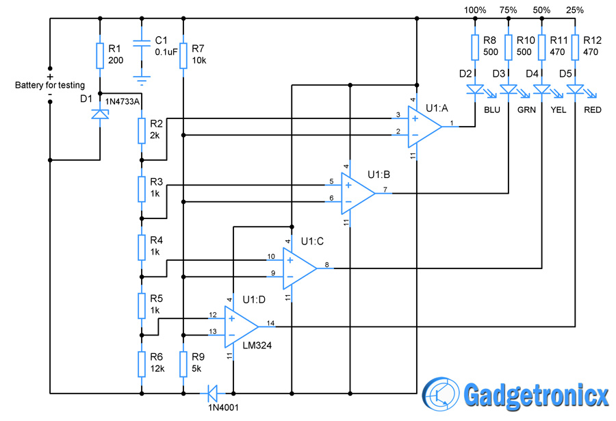
Battery Charging Indicator Circuit

Battery Full Charge Indicator Circuit Diagram Battery charge indicator circuit design in this circuit led’s (d1 d10) displays the capacity of the battery in either dot mode or display mode. this mode is selected by the external switch sw1 which is connected to 9 th pin of ic. 6 th and 7 th pins of ic are connected to the ground through a resistor. How to test and use. first, connect the 12v battery to the circuit’s input and adjust the pot rv1 until d1 starts emitting light. next, gradually increase the dc voltage input and watch the leds glow. the first led will shine at 1.2v, while the second will glow at 2.4v. when you reach 12v, all 10 leds will light.

Simple 12 Volt Battery Full Charge Indicator Circuit Youtube Simple battery charger circuit and battery level indicator with low battery recharge alarm. here demonstrated a simple 12v rechargeable smart battery charger circuit. you can use this battery charger circuit for multiple purposes such as car battery chargers, inverter battery chargers, emergency light battery chargers, etc. Step 1: assemble the hardware. connect the voltage divider circuit to the battery and the arduino’s analog input pin. wire the led bar graph to the arduino’s digital output pins. power the arduino using the battery or an external power source. Let’s design a simple circuit to know the percentage of charge in a battery. i am going to take a 12v li battery and keeping it as an example , the design the battery charge indicator circuit is explained below. now for a typical 12v battery the voltage at various charge levels will be. The 12v battery charging level indicator circuit uses a few basic components – a microcontroller, two resistors, and an led – to measure the voltage levels of the battery. this compact circuit can be connected directly to the positive and negative terminals of the battery, and provides information about the battery’s health from the led.

New 12 Volt Battery Full Charge Level Indicator Circuit Youtube Let’s design a simple circuit to know the percentage of charge in a battery. i am going to take a 12v li battery and keeping it as an example , the design the battery charge indicator circuit is explained below. now for a typical 12v battery the voltage at various charge levels will be. The 12v battery charging level indicator circuit uses a few basic components – a microcontroller, two resistors, and an led – to measure the voltage levels of the battery. this compact circuit can be connected directly to the positive and negative terminals of the battery, and provides information about the battery’s health from the led. 12v battery charge level indicator circuit led bar graph. the lm3914 is a monolithic integrated circuit that senses analog voltage levels and drives 10 leds, providing a linear analog display. this ic is used for dot and bar display. a single pin changes the display from a moving dot to a bar graph. the current drive to the leds is regulated. The relation between led and battery level is given below: led1 – 100% to 80%. led2 – 80% to 60%. led3 – 60% to 40%. led4 – 40% to 20%. led5 – 20% to 5%. led6 <5% (charge your battery) the arduino measures a narrow range of voltage from 12.70v to 11.90v. a fully charged battery should have voltage above 12.70v after disconnecting.

How To Design A Battery Charge Indicator Circuit Gadgetronicx 12v battery charge level indicator circuit led bar graph. the lm3914 is a monolithic integrated circuit that senses analog voltage levels and drives 10 leds, providing a linear analog display. this ic is used for dot and bar display. a single pin changes the display from a moving dot to a bar graph. the current drive to the leds is regulated. The relation between led and battery level is given below: led1 – 100% to 80%. led2 – 80% to 60%. led3 – 60% to 40%. led4 – 40% to 20%. led5 – 20% to 5%. led6 <5% (charge your battery) the arduino measures a narrow range of voltage from 12.70v to 11.90v. a fully charged battery should have voltage above 12.70v after disconnecting.

Comments are closed.