Condenser Unit Wiring Diagram

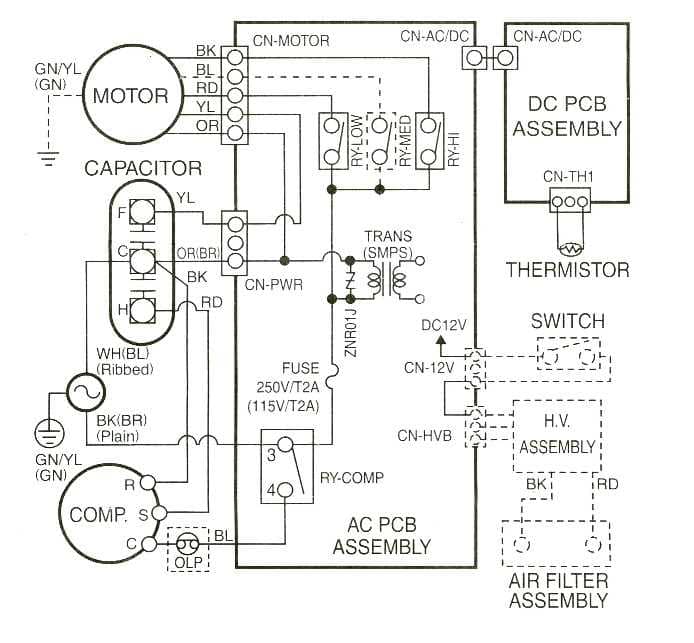
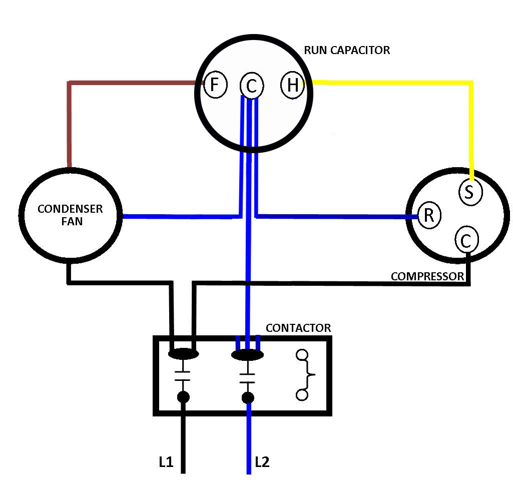
A C Condenser Wiring Diagram An ac condenser wire diagram is a visual representation of the wiring connections in an air conditioning condenser unit. the condenser unit is an essential component of any air conditioning system, as it helps to dissipate heat from the refrigerant and turn it back into a liquid state. the wire diagram provides a detailed overview of the. This is how to wire a 240 volt single phase condenser used for air conditioning. this includes where to install the high and low voltage wiring and why, how.

A C Condenser Unit Wiring Diagram The condenser wiring diagram is a schematic representation of the electrical connections and components involved in the functioning of the condenser unit. understanding the basic components of a condenser wiring diagram is crucial for troubleshooting and repairing any issues that may arise with the condenser unit. 1. 3.1 prepare the unit for installation step 1 check for damage and report prompt ly to the carrier any damage found to the unit. section 4. setting the unit 4.1 pad installation when installing the unit on a support pad, such as a concrete slab, consider the following: • the pad should be at least 1” larger than the unit on all sides. The wiring diagram for an hvac (heating, ventilation, and air conditioning) condenser is an important tool for understanding how the electrical components of the unit are connected. it provides a visual representation of the wiring connections and can be used by technicians for troubleshooting and installation purposes. For a visual picture of typical wiring configurations, reference the following guide: hvac condenser fan motor wiring diagram. finally, this guide is intended to be used as a general overview of common condenser unit wiring schematics. some condenser fan motors wire to a circuit board while others use proprietary plugs for their connectors.

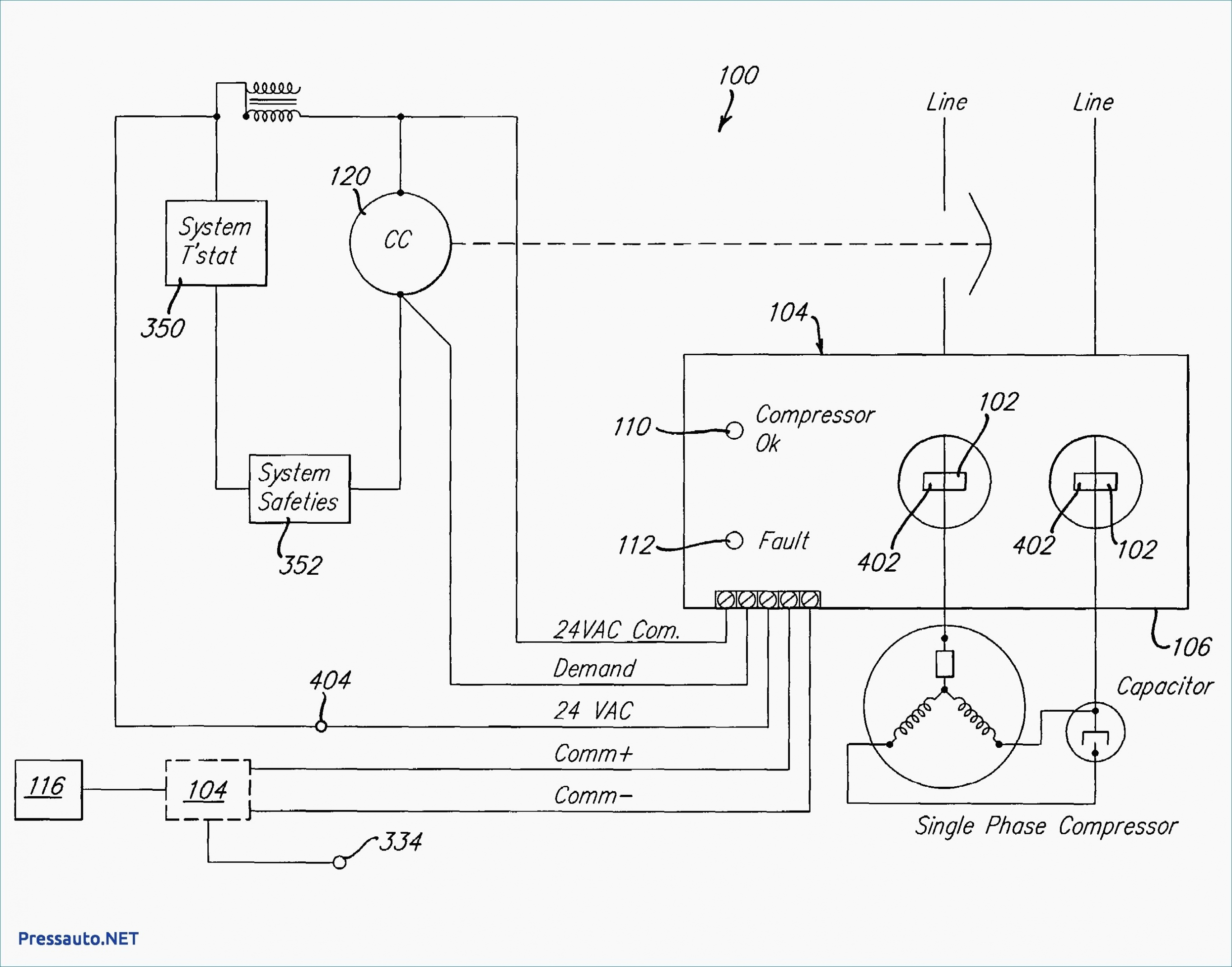
Ac Condenser Unit Wiring Diagram The wiring diagram for an hvac (heating, ventilation, and air conditioning) condenser is an important tool for understanding how the electrical components of the unit are connected. it provides a visual representation of the wiring connections and can be used by technicians for troubleshooting and installation purposes. For a visual picture of typical wiring configurations, reference the following guide: hvac condenser fan motor wiring diagram. finally, this guide is intended to be used as a general overview of common condenser unit wiring schematics. some condenser fan motors wire to a circuit board while others use proprietary plugs for their connectors. Refer to the wiring diagram included with your condenser for the proper wire identification. strip the wires: use the wire strippers to carefully strip the insulation off the ends of the wires. this will expose the bare copper wire for easier connection. connect the wires: follow the wiring diagram to connect the wires according to the. Loads. loads usually sit at the end of a circuit; after power moves from the power supply through an inline switch or switches, the load or loads are powered up and begin functioning. loads include motors, compressors, contactors, relay coils, and light bulbs. loads perform work and draw amperage. this basic wiring diagram includes all three.

Wiring For Ac Condenser Refer to the wiring diagram included with your condenser for the proper wire identification. strip the wires: use the wire strippers to carefully strip the insulation off the ends of the wires. this will expose the bare copper wire for easier connection. connect the wires: follow the wiring diagram to connect the wires according to the. Loads. loads usually sit at the end of a circuit; after power moves from the power supply through an inline switch or switches, the load or loads are powered up and begin functioning. loads include motors, compressors, contactors, relay coils, and light bulbs. loads perform work and draw amperage. this basic wiring diagram includes all three.

Comments are closed.