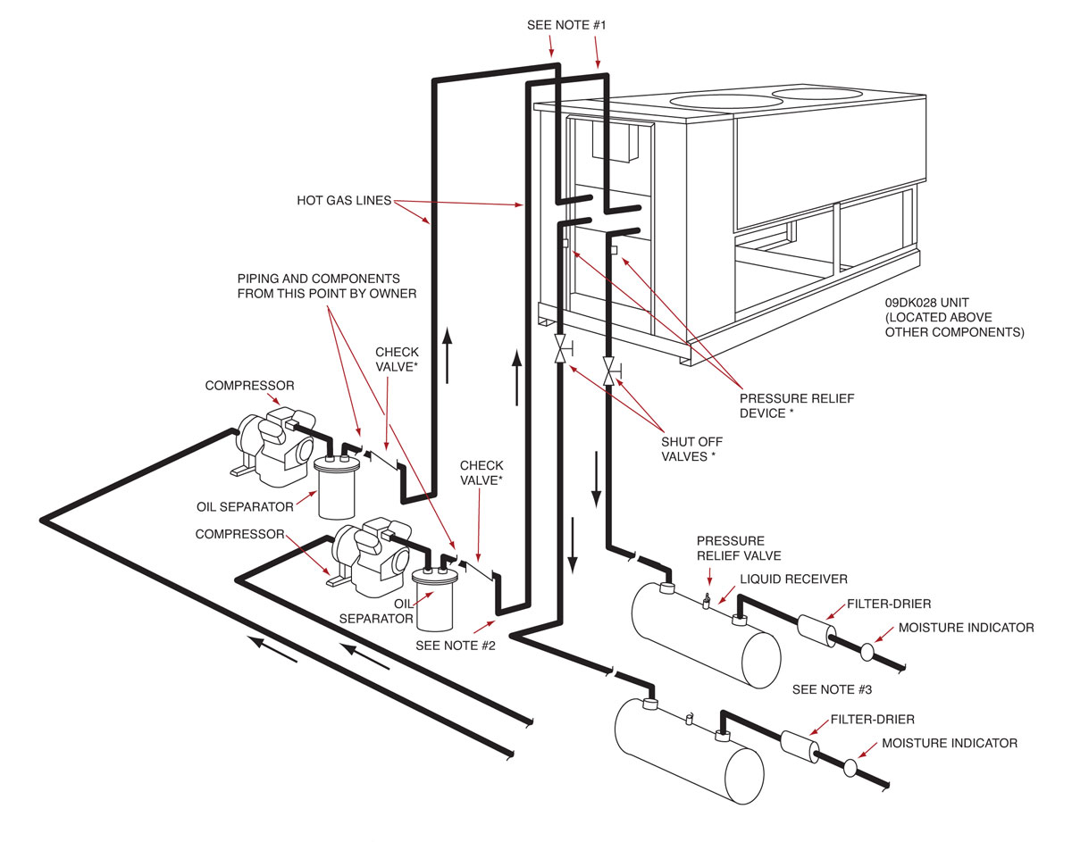
Condensing Unit Schematic

Schematic Diagram Of A Condensing Unit Download Scientific Diagram Step 2 remove the pressure tap cap and valve cores from both service valves. step 3 purge the refrigerant lines and indoor coil with dry nitrogen. step 4 wrap a wet rag around the valve body to avoid heat damage and continue the dry nitro gen purge. braze the refrigerant lines to the service valves. Wiring diagram cross reference condensing unit voltage evaporator voltage and type condensing unit type diagram number page diagram number page copeland scroll 208 230 1 60 230 air defrost low profile small scroll s2a1d a2 ka101 a13 208 230 3 60 230 electric defrost low profile small scroll t3a1a a3 lpe101 a14 208 230 3 60 2x 230 electric.

Condenser Unit Parts Diagram Condenser unit parts diagram. a condenser unit is an essential component of an air conditioning system that helps to release heat from the refrigerant. understanding the different parts of a condenser unit can be helpful for troubleshooting and maintenance purposes. 1. compressor. the compressor is often referred to as the heart of the. View and download goodman gsx technical manual online. gsx 13 seer series single phase condensing units with r 410a. gsx air conditioner pdf manual download. also for: gsx130181a, gsx130241a, gsx130301a, gsx130361a, gsx130421a, gsx130481a, gsx130601a, gsx130181b, gsx130241b,. Page 1: wiring diagrams. 38aks013 024 air cooled condensing units 50 60 hz wiring diagrams units produced after january 1996 index electrical schematic component label diagram unit characteristics diagram arrangement (on unit) 38aks (v ph hz) fig. no. fig. no. no. 38ak 208 230 3 60 501206 380 3 60 501206 230 3 50 501206 013 024. Rnal surfaces of the tubing using an emery cloth.step 2 remove the pressur. tap cap and valve cores from both service valves.step 3 purge the r. frigerant lines and indoor coil with dry nitrogen.step 4 wrap a wet rag around the valve body to avo. d heat damage and continue the dry nitrogen purge.

Comments are closed.