Demand Cooling Module Wiring Diagram

Demand Cooling Components Market Service Tech Demand cooling is designed to work on all copeland discus compressors equipped with injection ports. a different kit is required for each compressor body style and control voltage. see table 2 for a listing of demand cooling kit part numbers. the system must be clean. Figure 5: wiring diagram for liquid injection and or head fan monitored via module c 4 demand cooling application the demand cooling system should be considered as the back up for a well designed low temperature refrigeration system. normally the demand cooling valve only operates during high condensing temperature conditions. the refrigerant.

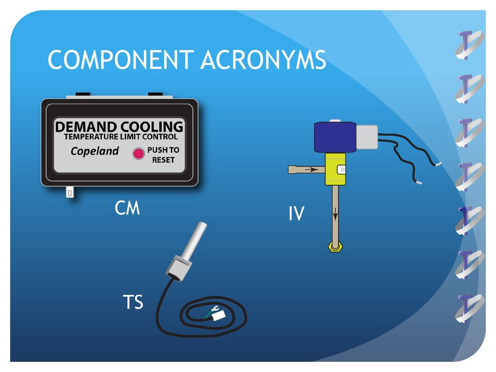
Demand Cooling Copeland Discus Demand Cooling Ppt Download Pg.25 – “demand cooling for scroll” section changed adding notes about parts phased out for this system. this section was moved as a appendix at the end. pg. 10 – 998 0166 00 kit drawing added. pg. 10 – explanation about zf**kve digital model , including new figures. pg. 12 –dtc valve section for zf*kve compressors. The demand cooling driver controls the liquid injection and also behaves as an alarm. 4.2.1 liquid injection control injection start: sensor resistance < 2100 ohms (t > 140°c); demand cooling on injection stop: sensor resistance > 2400 ohms (t > 130°c); demand cooling off 4.2.2 modulating output for demand cooling. Supply voltage to the digital compressor controller has dropped below 18.5vac. the digital compressor controller will deenergize the compressor contactor, unloader solenoid and vapor injection solenoid. the alarm relay contacts may close if the voltage is high enough for the alarm relay to pullin. The alarm signal for local or remote control. the alarm relay is energized, after a one minute delay, by a continuous, low or high ts temperature signal. an alarm signal can indicate the following: compressor discharge temperature has risen above the level designed to be controlled by demand cooling. a shorted sensor.

Demand Cooling Components Market Service Tech Supply voltage to the digital compressor controller has dropped below 18.5vac. the digital compressor controller will deenergize the compressor contactor, unloader solenoid and vapor injection solenoid. the alarm relay contacts may close if the voltage is high enough for the alarm relay to pullin. The alarm signal for local or remote control. the alarm relay is energized, after a one minute delay, by a continuous, low or high ts temperature signal. an alarm signal can indicate the following: compressor discharge temperature has risen above the level designed to be controlled by demand cooling. a shorted sensor. The power supply for the digital compressor controller is 19 28vac, 48 62hz. the maximum load is 2 va. the 24vac phasing for the digital compressor controller must match the system controller to avoid a transformer short circuit condition because the two controllers have their commons connected together. Assembly must be in accordance with the position of the relay shown on the wiring diagram. 4.2.2 three phase motors all compressors can be started direct on line. the necessary position of bridges for direct on line start (depending on type of motor and or mains voltage) is shown on the principle wiring in section 4.3.1. page 23: motor protection.

Demand Cooling Copeland Discus Demand Cooling Ppt Download The power supply for the digital compressor controller is 19 28vac, 48 62hz. the maximum load is 2 va. the 24vac phasing for the digital compressor controller must match the system controller to avoid a transformer short circuit condition because the two controllers have their commons connected together. Assembly must be in accordance with the position of the relay shown on the wiring diagram. 4.2.2 three phase motors all compressors can be started direct on line. the necessary position of bridges for direct on line start (depending on type of motor and or mains voltage) is shown on the principle wiring in section 4.3.1. page 23: motor protection.

Comments are closed.