Design Of Bush Pin Type Coupling Formula Design Of Shaf

Explain The Design Procedure Of Bush Pin Type Flexible Coupling With Subject machine design 1video name design of bush pin type coupling formulachapter design of shaft, keys and couplingsfaculty prof. aniket patilwatch. Subject engineering mechanicsvideo name design of bush pin type coupling numerical part 01 chapter design of shaft, keys and couplingsfaculty prof.

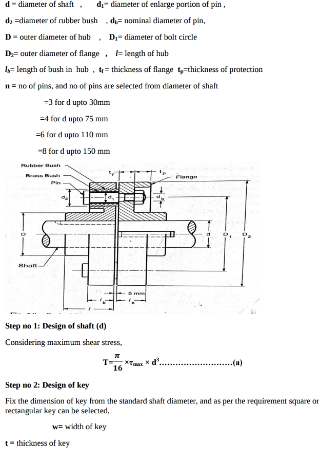
Design Of Bush Pin Type Coupling Formulae Design Of Shaft Pin & bush couplingcone ring couplings are based on a. time proven design. the coupling consists of two flanges interlocked with a number of elements, depending o. the coupling size.the cone ring couplings unique flexible element comprises tapered rubber rings mo. nted on steel pins. the rubber rings absorb commonly encountered misalignment,. Fig 5.3 (a) taper bush (b) locking assembly (shaft or bush connectors) (c) friction joint bushing (d) safety overload coupling. [source: “a textbook of machine design by r.s. khurmi j.k. gupta, page: 500] problem 5.1 design a bushed pin type of flexible coupling to connect a pump shaft to a motor shaft transmitting 32 kw at 960 r.p.m. Q.1: design a typical rigid flange coupling for connecting a motor and a centrifugal pump shafts. the coupling needs to transmit 15 kw at 1000 rpm. the allowable shear stresses of the shaft, key and bolt materials are 60 mpa,50 mpa and 25 mpa respectively. the shear modulus of the shaft material may be taken as 84gpa. To design a b ushed pin type flexible coupli ng fo r alloy steel shaft transmitting 40 kw at 1000 r.p.m. th e bearing pressure in the rubber bush and allowable shear stress in the pins are to be 0.

Design Of Bush Pin Type Coupling Formula Design Of Shaf Q.1: design a typical rigid flange coupling for connecting a motor and a centrifugal pump shafts. the coupling needs to transmit 15 kw at 1000 rpm. the allowable shear stresses of the shaft, key and bolt materials are 60 mpa,50 mpa and 25 mpa respectively. the shear modulus of the shaft material may be taken as 84gpa. To design a b ushed pin type flexible coupli ng fo r alloy steel shaft transmitting 40 kw at 1000 r.p.m. th e bearing pressure in the rubber bush and allowable shear stress in the pins are to be 0. Note: after designing the pins and rubber bush, the hub, key and flange may be designed in the similar way as discussed for flange coupling. example 13.12. design a bushed pin type of flexible coupling to connect a pump shaft to a motor shaft transmitting 32 kw at 960 r.p.m. the overall torque is 20 percent more than mean torque. Download scientific diagram | bush pin coupling (a) dimensions design calculation of coupling the bush pin coupling for the blower is designed and the calculations are follows power in shaft of.

Comments are closed.