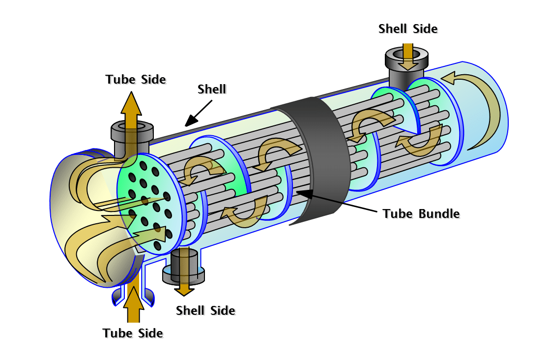
Design Of Shell And Tube Heat Exchanger Animation By Ocs Www

Design Of Shell And Tube Heat Exchanger Animation By Ocs Www This video is a part of "synthesis gas preparation" e learning module developed by ocs (www.octavesim portfolio) for details on the full product, contact. This is a very important parameter for heat exchanger design. generally, for liquids, a value of 0.5–0.7 kg cm2is permitted per shell. ahigher pressure drop is usually war ranted for viscous liquids, especially in the tubeside. for gases, the allowed value is generally 0.05–0.2 kg cm2, with 0.1 kg cm2being typical. 5.

Heat Exchanger Design Animation By Ocs Www Octavesim Youtube Shell and tube heat exchanger removal and cleaning. design of shell and tube heat exchanger, animation by ocs. spiral heat exchanger flow simulation. Shell & tube heat exchangers are the most versatile type of heat exchangers. they are used in process industries, in conventional and nuclear power stations, steam generators, etc. they are used in many alternative energy applications including ocean, thermal and geothermal. shell & tube heat exchangers provide relatively large ratios of heat. The specific name of this document is the “thermal design report” or “thermal design calculation sheet.” these documents typically outline the calculations, methodologies, and results of the thermal design phase for the shell and tube heat exchanger. the thermal design report may include sections such as:. For exchanger tubing, the outside tube diameter is fixed. the inside diameter varies with the nominal wall thickness and wall thickness tolerance. tube ods range from small tubes of ½” to 2” size. usual tube od is ¾” chosen. tema gives eight tube diameters: 9.525mm, 12.7mm, 15.875mm, 19.05mm, 25.4mm, 31.75mm, 38.1mm & 50.8mm.

Shell And Tube Heat Exchanger Animation Youtube The specific name of this document is the “thermal design report” or “thermal design calculation sheet.” these documents typically outline the calculations, methodologies, and results of the thermal design phase for the shell and tube heat exchanger. the thermal design report may include sections such as:. For exchanger tubing, the outside tube diameter is fixed. the inside diameter varies with the nominal wall thickness and wall thickness tolerance. tube ods range from small tubes of ½” to 2” size. usual tube od is ¾” chosen. tema gives eight tube diameters: 9.525mm, 12.7mm, 15.875mm, 19.05mm, 25.4mm, 31.75mm, 38.1mm & 50.8mm. (upstream of waste heat boiler)economizer design data are as mentioned below: shell design pressure 34 bar boiler feed water service moc ss304 tube design pressure 8.27 bar nox gases moc ss321 during boiler testing inspection (i.e. ibr) at high pressure i.e at 51 bar (1.5 * 34) my economizer tubes got bursted. From the tube bundle to the shell, witness the automated assembly process, and grasp the working principles behind this essential piece of engineering. 🚀 key highlights: automated assembly demonstration part by part animation working principle overview essential part names revealed 🔍 timestamps: 0:00 start 0:10 tube bundle assembly.

Shell And Tube Heat Exchanger Animation Fundamentals Youtube (upstream of waste heat boiler)economizer design data are as mentioned below: shell design pressure 34 bar boiler feed water service moc ss304 tube design pressure 8.27 bar nox gases moc ss321 during boiler testing inspection (i.e. ibr) at high pressure i.e at 51 bar (1.5 * 34) my economizer tubes got bursted. From the tube bundle to the shell, witness the automated assembly process, and grasp the working principles behind this essential piece of engineering. 🚀 key highlights: automated assembly demonstration part by part animation working principle overview essential part names revealed 🔍 timestamps: 0:00 start 0:10 tube bundle assembly.

Shell And Tube Heat Exchanger Schematic Diagram

Comments are closed.