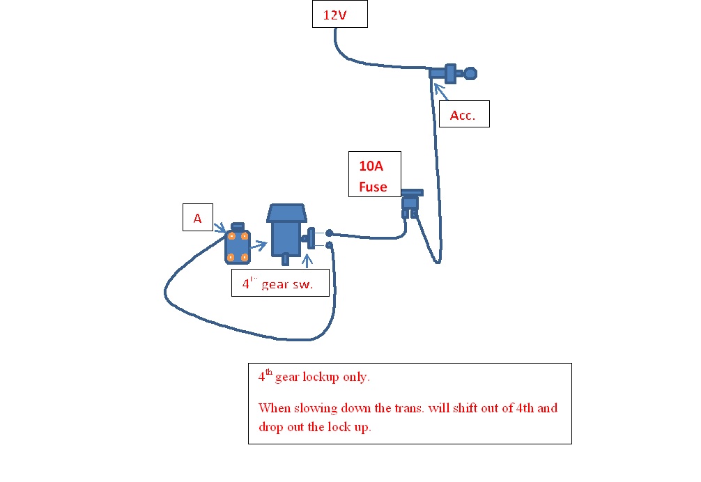
Diagram 700r4 Tcc Lockup Diagram Mydiagram Online

Diagram 700r4 Tcc Lockup Diagram Mydiagram Online Share. tweet. #1. 700r4 tcc lockup wiring. september 4, 2011, 12:09 pm. here is a diagram from tci i believe: here is a diagram and a picture (several pics collaged together)of what found when i dropped my trans pan: normally, i believe that pin a is 12 volts, and pin d is ground. is this still the case in my situation, based on the diagram of. Step 2: locate the transmission connector. next, locate the transmission connector on the driver’s side of the transmission. this connector is typically round or square in shape and contains several pins. referencing your wiring diagram, identify the correct pins that correspond to the torque converter lockup system.

Diagram 700r4 Tcc Lockup Diagram Mydiagram Online Reasoning is that the internals might have those switches to make sure that you are in 4th gear for the lockup to happen. if you bypass this (grounding like you suggest) it will probably hurt the trans and tcc. try running a fused 12v to terminal 420 and see if the lockup works right. So my truck came factory with the 700r4. from the factory 3rd gear lockup was controlled by the vacuum switch, and over drive is always locked, unless the brake pedal is depressed. so all i really did was disconnected the vacuum switch wiring and wired it to a switch so i could manually control 3rd gear lockup. Fig. 3 fuse holder, manual switch, oil switch, lock up plug let's test the lockup solenoid first we will verify if the transmissions lockup solenoid is functioning and if it's a 2 wire or a 1 wire solenoid. 1. connect the transmission connector plug to the transmission plug on the driver side and be sure it is plugged in securely. 2. Remove the wires from the clips and unplug the wiring harness from the connector near the detent roller spring. pry connector tab away from the plug and pull the plug down. do not pull on the wires. step 3 based on your application, find the wiring diagram to determine the proper fourth gear pressure switch location.

Comments are closed.