Diagram Cooling Transformation

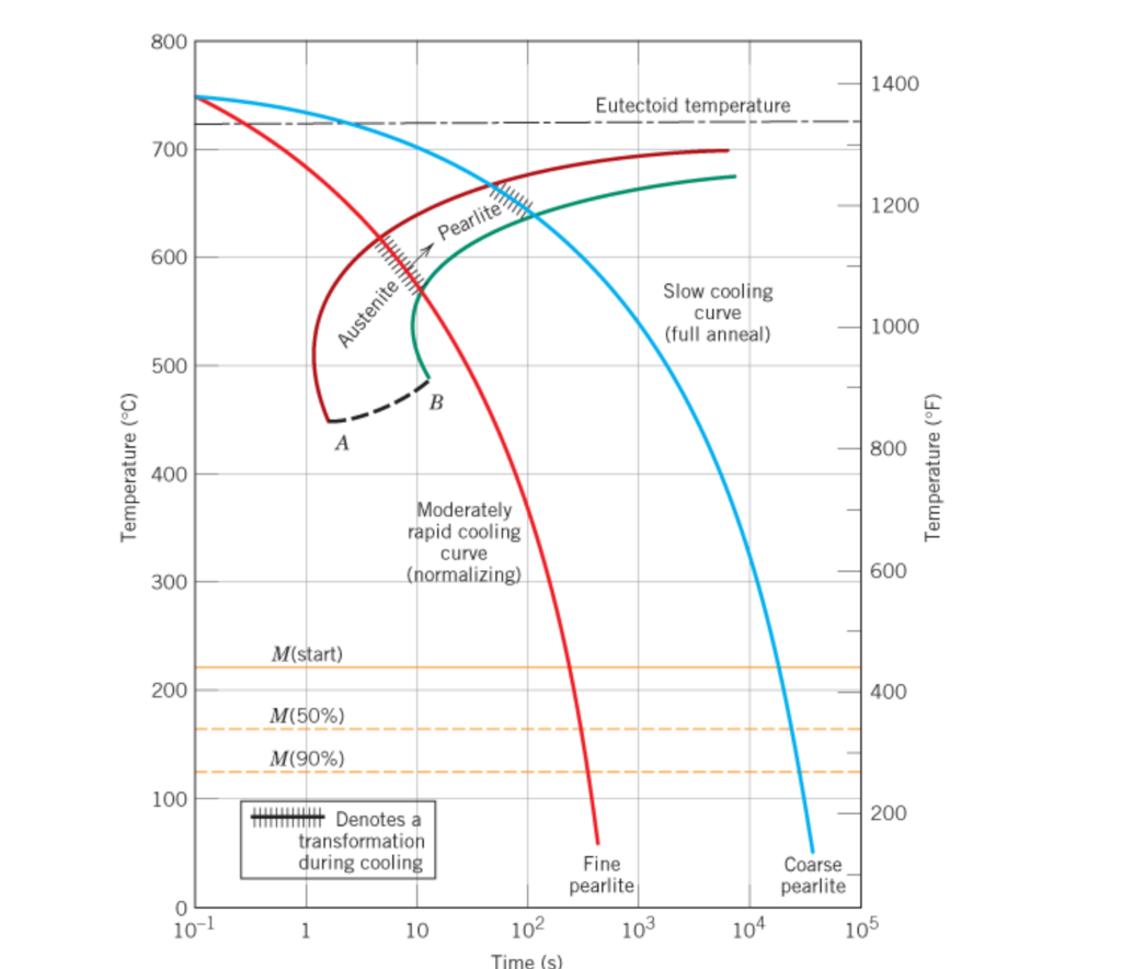
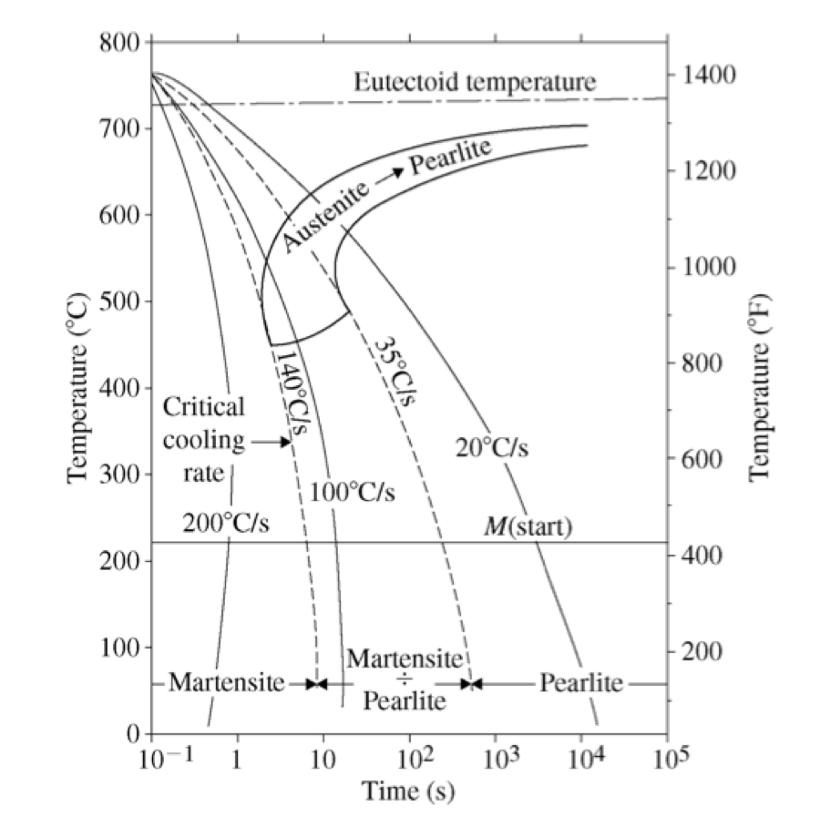
Schematic Illustration Of Continuous Cooling Transformation Cct A continuous cooling transformation (cct) phase diagram is often used when heat treating steel. [ 1 ] these diagrams are used to represent which types of phase changes will occur in a material as it is cooled at different rates. these diagrams are often more useful than time temperature transformation diagrams because it is more convenient to. Definition: stability of phases during continuous cooling of austenite. there are two types of cct diagrams. i) plot of (for each type of transformation) transformation start, specific fraction of transformation and transformation finish temperature against transformation time on each cooling curve.

Continuous Cooling Transformation Diagram Figure 7. cooling rate that permits both pearlite and martensite formation. sometimes the cooling curve may pass through the middle of the austenite pearlite transformation zone. in figure 7, cooling curve e indicates a cooling rate which is not high enough to produce 100% martensite. this can be observed easily by looking at the ttt diagram. These diagrams are called continuous cooling transformation (cct) diagrams actually a ttt diagram can be easily determined needing relatively simple experimental set up and metallographic equipment. for these reasons, though the usefulness of cct diagram was realised quite long back, most of the early work on the transformation in steels has. A ttt diagram, also known as a time temperature transformation diagram, is an important tool used in metallurgy and materials science to understand the transformation behavior of materials over time and temperature. this diagram provides valuable information about the kinetics and phases that occur during cooling or heating processes, helping engineers and researchers predict the. There are two main types of transformation diagram that are helpful in selecting the optimum steel and processing route to achieve a given set of properties. these are time temperature transformation (ttt) and continuous cooling transformation (cct) diagrams. cct diagrams are generally more appropriate for engineering applications as components.

A Continuous Cooling Transformation Diagram And B Download A ttt diagram, also known as a time temperature transformation diagram, is an important tool used in metallurgy and materials science to understand the transformation behavior of materials over time and temperature. this diagram provides valuable information about the kinetics and phases that occur during cooling or heating processes, helping engineers and researchers predict the. There are two main types of transformation diagram that are helpful in selecting the optimum steel and processing route to achieve a given set of properties. these are time temperature transformation (ttt) and continuous cooling transformation (cct) diagrams. cct diagrams are generally more appropriate for engineering applications as components. 1. introduction. to evaluate the performance of structural steels, understanding its microstructure after processing is crucial. the continuous cooling transformation (cct) diagram of a steel plays an important role in providing information on the steel microstructure, as the information includes the start temperatures of phase transformation during cooling, as well as hardness. Continuous cooling transformation (cct) diagrams are widely used when heat treating steels and represent which type of phase will occur in a material as it is cooled at different cooling rates. cct diagrams are constructed on the basis of dilatometry measurements on relatively small testing samples (cylindrical shape with diameter of 4mm and length of 11 mm in this study). the main aim of this.

Continuous Cooling Transformation Diagram 1. introduction. to evaluate the performance of structural steels, understanding its microstructure after processing is crucial. the continuous cooling transformation (cct) diagram of a steel plays an important role in providing information on the steel microstructure, as the information includes the start temperatures of phase transformation during cooling, as well as hardness. Continuous cooling transformation (cct) diagrams are widely used when heat treating steels and represent which type of phase will occur in a material as it is cooled at different cooling rates. cct diagrams are constructed on the basis of dilatometry measurements on relatively small testing samples (cylindrical shape with diameter of 4mm and length of 11 mm in this study). the main aim of this.

Comments are closed.