Diagram T S Diagram Steam Pdf Mydiagram Online

Diagram T S Diagram Steam Pdf Mydiagram Online Online interactive p h and t s diagram. please allow more processing time for mixed refrigerant. submit all changes below. click on diagram for properties. or input data for properties. pressure, bar. enthalpy, kj kg. quantity. value. The results revealed that when the conventional steam power plant became multigeneration, the exergy efficiency increased from 39.1% to 39.84% and energy efficiency increased from 41.5% to 42.29%.

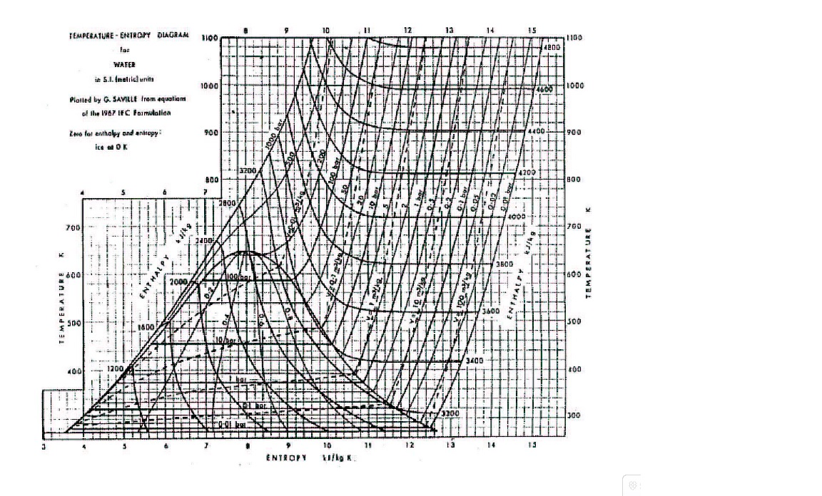
Diagram T S Diagram Steam Pdf Mydiagram Online Temperature entropy (t s) diagram. figure 1 t s diagram for water. in the liquid vapor region in figure 1, water and steam exist together. for example, at point a, water with an entropy (s f) given by point b, exists together with steam with an entropy (s g) given by point c. the quality of the mixture at any point in the liquid vapor region. The t s diagram is one of the most used plots in thermodynamics. it is used to analyze vapor power cycles, gas power cycles, and gas refrigeration cycles along with the p v diagram. hence it becomes really important to understand the t s diagram. once you understand it, applied thermodynamics becomes easier to interpret and analyze. Designation of figure 1 is used to analyse the cycle. the net power output and efficiency of the cycle are given by, the heat transfer in the condenser is given as [6] ) 5 ( for the sake of. Hf = enthalpy at 400°c and 1 atm., as read from the mollier diagram = 3280 kj kg. then, using the mollier diagram, the amount of heat that must be removed from the system in order to lower the temperature from 450°c to 400°c, at 1 atm, would be: ∆h = hi hf = 3380 kj kg 3280 kj kg = 100 kj kg.

Comments are closed.