Difference Parallel And Series Circuit

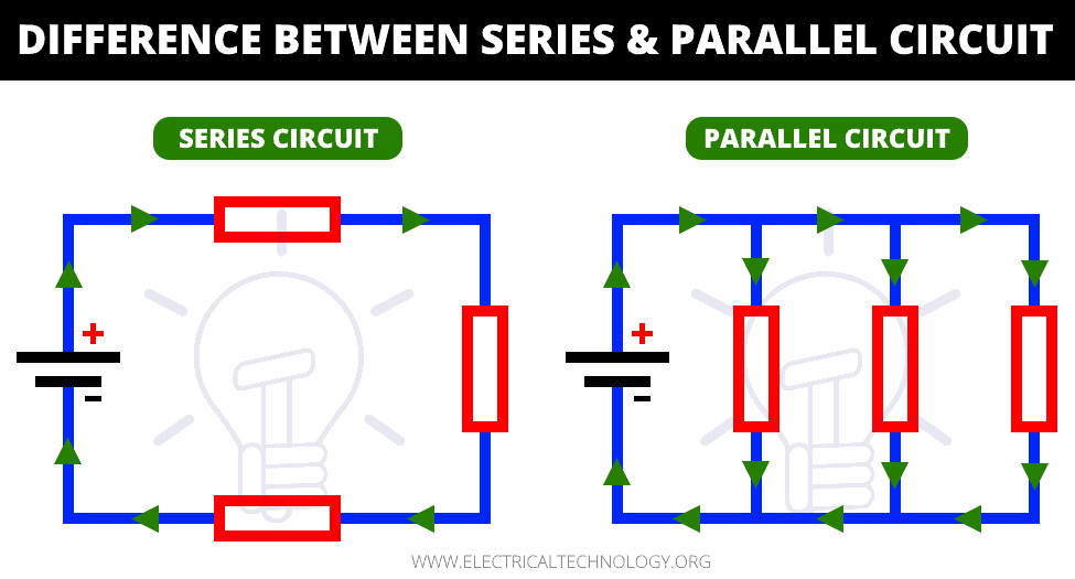
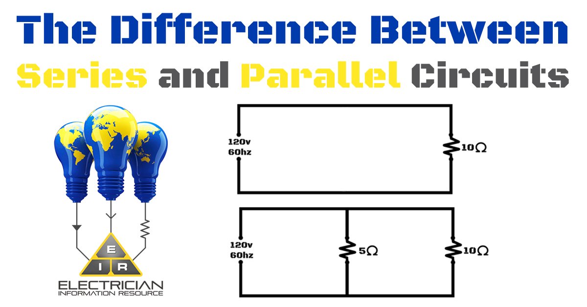
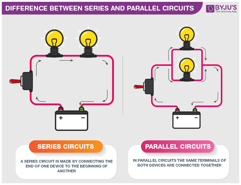
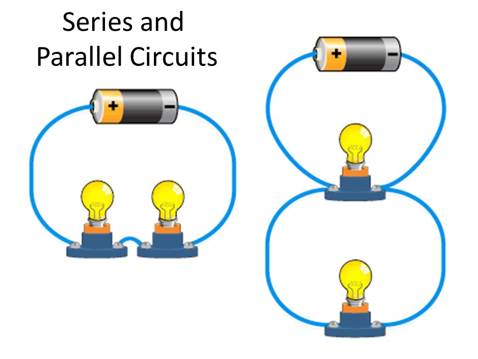
Difference Between A Parallel And Series Circuit The major difference between series and the parallel circuit is the amount of current that flows through each of the components in the circuit. in a series circuit, the same amount of current flows through all the components placed in it. on the other hand, in parallel circuits, the components are placed in parallel with each other due to which. All of the resistors, as well as the battery, are connected between these two sets of points. this means that the same voltage (v) is dropped across all components in a parallel circuit. series vs parallel circuit review: in a series circuit, all components are connected end to end, forming a single path for current flow.

Series And Parallel Circuit Electrician School The circuit carries current only if all switches are closed (on). but in a parallel circuit, two or more switches make a logical or gate. current flows as long as any one of the switches is closed. references. series and parallel circuits ; introduction to circuits: parallel and series circuits. A parallel circuit is like a freeway. ramps allow cars to exit and enter a freeway without interrupting the main highway. a parallel circuit has many off and on ramps. a failure in any single loop never shuts down the entire circuit. a series circuit is like a circular road with multiple bridges. Series and parallel circuits. a series circuit with a voltage source (such as a battery, or in this case a cell) and three resistance units. two terminal components and electrical networks can be connected in series or parallel. the resulting electrical network will have two terminals, and itself can participate in a series or parallel topology. Understanding the distinction between series and parallel circuits is fundamental for anyone delving into electronics, whether a student, hobbyist, or professional. these two types of circuits represent the basic building blocks of electrical networks. their differences lie in their configuration and how they affect the flow of electricity.

Diagram Of Series And Parallel Circuit Series and parallel circuits. a series circuit with a voltage source (such as a battery, or in this case a cell) and three resistance units. two terminal components and electrical networks can be connected in series or parallel. the resulting electrical network will have two terminals, and itself can participate in a series or parallel topology. Understanding the distinction between series and parallel circuits is fundamental for anyone delving into electronics, whether a student, hobbyist, or professional. these two types of circuits represent the basic building blocks of electrical networks. their differences lie in their configuration and how they affect the flow of electricity. In this tutorial, we’ll first discuss the difference between series circuits and parallel circuits, using circuits containing the most basic of components resistors and batteries to show the difference between the two configurations. we’ll then explore what happens in series and parallel circuits when you combine different types of. 1 r = 1 r1 1 r2 r = (1 r1 1 r2) − 1. [equivalent resistance of two resistors in parallel] two resistors in parallel, c 4, are equivalent to a single resistor with a value given by the above equation. example 10: two lamps on the same household circuit. you turn on two lamps that are on the same household circuit.

Series And Parallel Circuits Top 5 Differences Circuit Diagram And In this tutorial, we’ll first discuss the difference between series circuits and parallel circuits, using circuits containing the most basic of components resistors and batteries to show the difference between the two configurations. we’ll then explore what happens in series and parallel circuits when you combine different types of. 1 r = 1 r1 1 r2 r = (1 r1 1 r2) − 1. [equivalent resistance of two resistors in parallel] two resistors in parallel, c 4, are equivalent to a single resistor with a value given by the above equation. example 10: two lamps on the same household circuit. you turn on two lamps that are on the same household circuit.

Difference Between A Series Circuit And A Parallel Circuit

Comments are closed.