Entity Relationship Diagram Explanation Ermodelexample

Er Diagram Tutorial Complete Guide To Entity Relationship Er diagram stands for entity relationship diagram, also known as erd is a diagram that displays the relationship of entity sets stored in a database. in other words, er diagrams help to explain the logical structure of databases. er diagrams are created based on three basic concepts: entities, attributes and relationships. Introduction of er model. peter chen developed the er diagram in 1976. the er model was created to provide a simple and understandable model for representing the structure and logic of databases. it has since evolved into variations such as the enhanced er model and the object relationship model. the entity relational model is a model for.

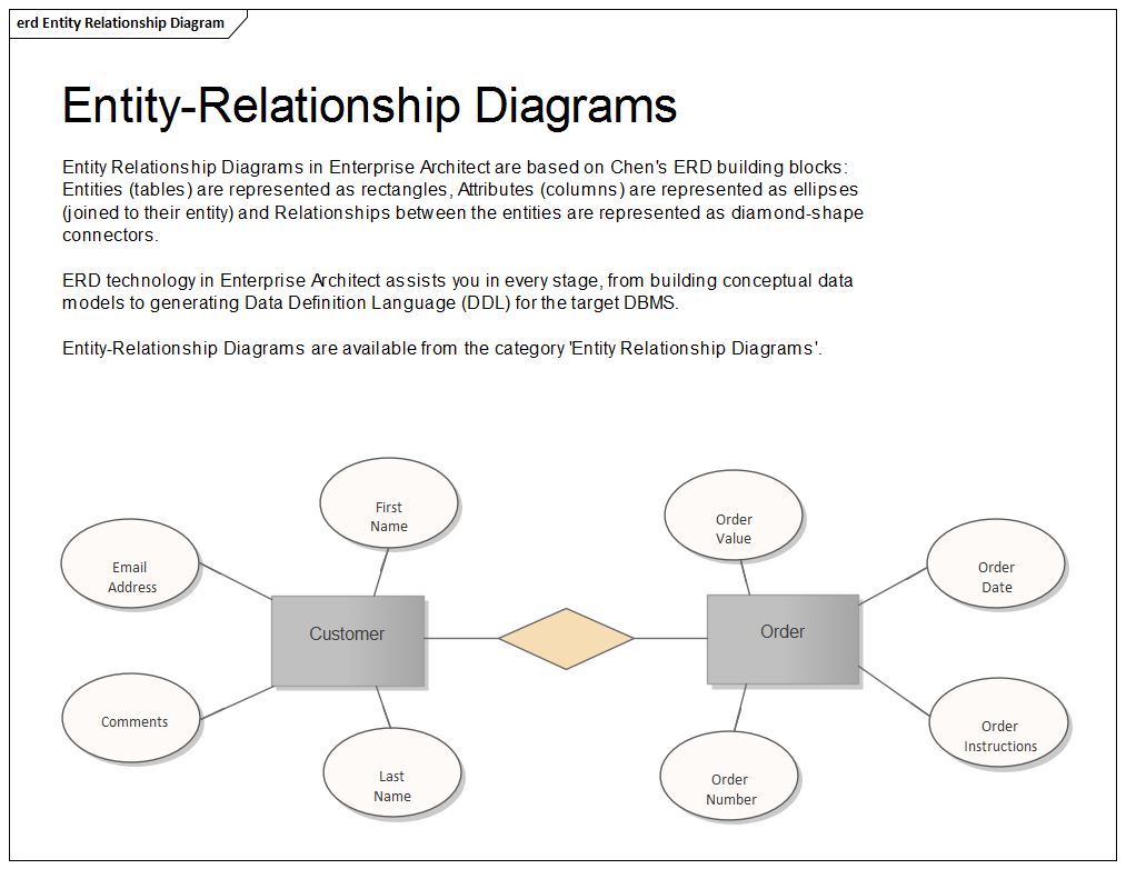
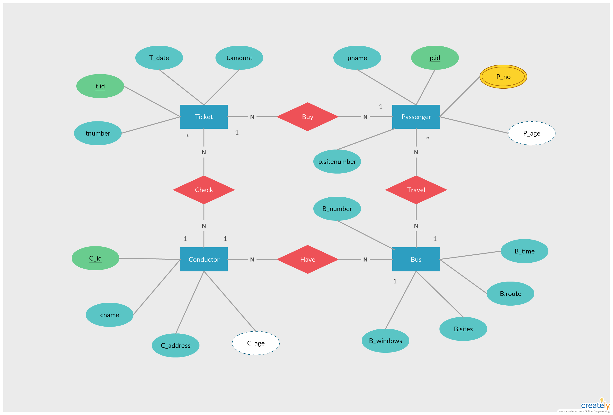
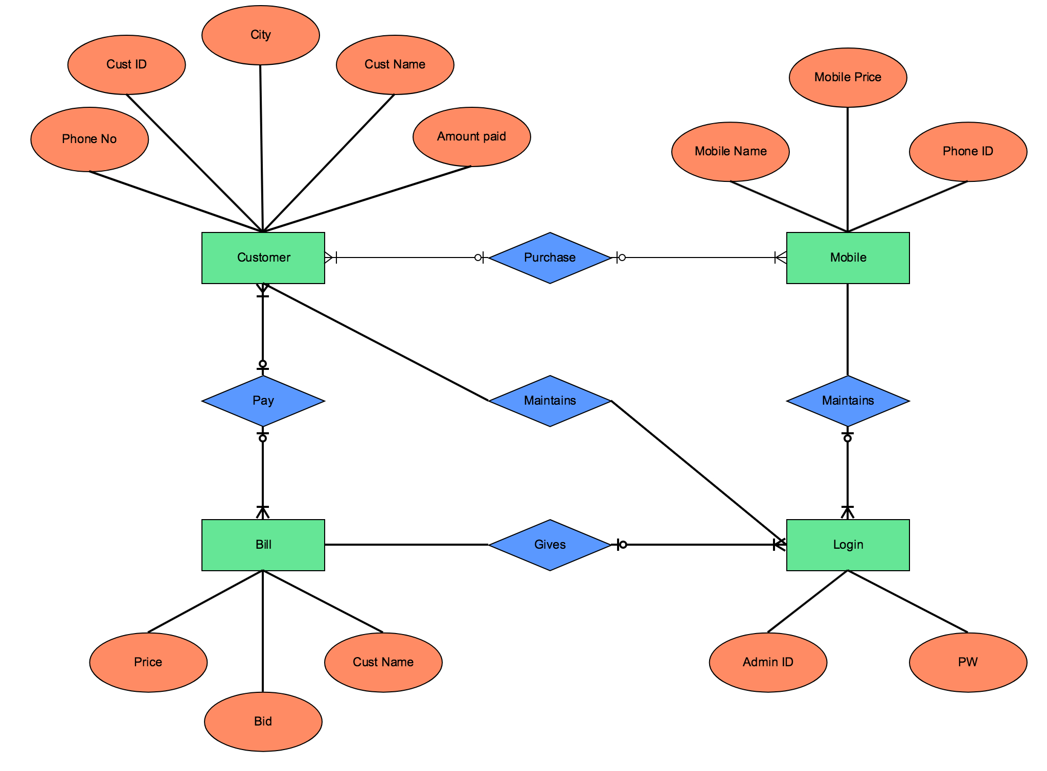
Entity Relationship Model Diagram Ermodelexample How to draw an er diagram. let’s create an er diagram for a data model using vertabelo. consider a simple scenario in which a client orders food at a restaurant. the client must purchase one or more menu items, while each menu item is served by one attendant. 1. first, identify the entities in your database. Introduction. entity relationship (er) modeling is a powerful tool for designing and representing complex data systems. this modeling technique allows developers to visualize the relationships between different entities in a system and the attributes associated with them. er modeling is widely used in software engineering, database design, and. Entity relationship diagram (er diagram or erd) is a pictorial or visual representation of classifying groups or entities of common interest and defining the relationship between these groups. hence, a structure is created with various symbols of different shapes and sizes so that it can be used as a model to depict the internal structure. Entity relationship diagrams use a specific set of symbols, such as shapes and arrows, to depict the system and database. here’s an example of an erd: components of an erd. an entity relationship diagram is made up of many different components: entity; relationship; attribute . entity. an entity is a thing that can have data stored about it.

Er Diagram Theory Ermodelexample Entity relationship diagram (er diagram or erd) is a pictorial or visual representation of classifying groups or entities of common interest and defining the relationship between these groups. hence, a structure is created with various symbols of different shapes and sizes so that it can be used as a model to depict the internal structure. Entity relationship diagrams use a specific set of symbols, such as shapes and arrows, to depict the system and database. here’s an example of an erd: components of an erd. an entity relationship diagram is made up of many different components: entity; relationship; attribute . entity. an entity is a thing that can have data stored about it. Entity relationship diagram, also known as erd, er diagram or er model, is a type of structural diagram for use in database design. an erd contains different symbols and connectors that visualize two important information: the major entities within the system scope, and the inter relationships among these entities. An entity relationship (er) diagram is a type of flowchart that illustrates how “entities” such as people, objects or concepts relate to each other within a system. er diagrams are most often used to design or debug relational databases in the fields of software engineering, business information systems, education and research.

Basic Er Diagram Examples Ermodelexample Entity relationship diagram, also known as erd, er diagram or er model, is a type of structural diagram for use in database design. an erd contains different symbols and connectors that visualize two important information: the major entities within the system scope, and the inter relationships among these entities. An entity relationship (er) diagram is a type of flowchart that illustrates how “entities” such as people, objects or concepts relate to each other within a system. er diagrams are most often used to design or debug relational databases in the fields of software engineering, business information systems, education and research.

Comments are closed.