Fast Cooling Solidification Eutectic Phase Diagram
:max_bytes(150000):strip_icc()/eutectic-system-phase-diagram-56a135273df78cf7726863ea.png)
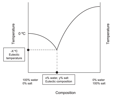
Eutectic Definition And Examples A eutectic system or eutectic mixture ( juːˈtɛktɪk yoo tek tik) [1] is a type of a homogeneous mixture that has a melting point lower than those of the constituents. [2] the lowest possible melting point over all of the mixing ratios of the constituents is called the eutectic temperature. on a phase diagram, the eutectic temperature is. By removing the time axis from the curves and replacing it with composition, the cooling curves indicate the temperatures of the solidus and liquidus for a given composition. this allows the solidus and liquidus to be plotted to produce the phase diagram: this page titled 12.5: interpretation of cooling curves is shared under a cc by nc sa.

Eutectic Solution Eutectic phase diagram • the cooling curve for an eutectic alloy is a simple thermal arrest. • please note that eutectics melt or freeze at single temperature whereas another composition like 30 wt% sn experience primary solidification before the eutectic transformation mech 221 lecture 26 3 dr. m. medraj mech. eng. dept. concordia university. Mse 2090: introduction to materials science chapter 9, phase diagrams 24 binary eutectic systems (iii) lead – tin phase diagram invariant or eutectic point eutectic isotherm temperature, ° c composition, wt% sn eutectic or invariant point liquid and two solid phases co exist in equilibrium at the eutectic composition ce and the eutectic. Figure 3 represents a phase diagram of a typical binary eutectic system. it gives the temperature range over which solidification takes place in an alloy belonging to this system. it has 3 two phase and 3 single phase regions separated by boundaries having specific names. Phase diagrams 2 eutectic reactions. the free energy curves and phase diagrams discussed in phase diagrams 1 were all for systems where the solid exists as a solution at all compositions and temperatures. in most real systems this is not the case. this is due to a positive Δ h m i x caused by unfavourable interactions between unlike.

Practical Maintenance в Blog Archive в Phase Diagrams Part 2 Figure 3 represents a phase diagram of a typical binary eutectic system. it gives the temperature range over which solidification takes place in an alloy belonging to this system. it has 3 two phase and 3 single phase regions separated by boundaries having specific names. Phase diagrams 2 eutectic reactions. the free energy curves and phase diagrams discussed in phase diagrams 1 were all for systems where the solid exists as a solution at all compositions and temperatures. in most real systems this is not the case. this is due to a positive Δ h m i x caused by unfavourable interactions between unlike. As a result, a series of cooling curves (fig. 10.11a) are obtained and used to construct an isomorphous binary phase diagram as shown in fig. 10.11b, which is a simple map of the liquid phase (l phase) having completely soluble a and b metals, a substitutional solid solution \(\alpha \) phase having a homogeneous microstructure and a mushy zone composed of \(l s\) phases. moreover, an. 12.4: phase diagrams. free energy curves can be used to determine the most stable state for a system, i.e. the phase or phase mixture with the lowest free energy for a given temperature and composition. below is a schematic free energy curve for the solid phase of an alloy. the solid shown could either exist as a mixture or as a homogeneous.

Comments are closed.