Fluid Flow 4l60e Transmission Cooler Lines Diagram

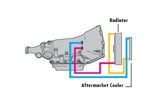
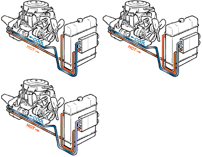
4l60e Transmission Cooler Line Diagram Flow Direction Cpt4l60e The 4l60e transmission cooler line flow is very easy to follow. as the gif above shows, the bottom line is the hot line which sends warm transmission fluid out to the factory trans cooler within the radiator at the lower port in most cases. fyi, some vehicles have the factory cooler on the bottom of the radiator, but simply follow the lower. This diagram is essential for understanding how the cooler lines connect to the transmission and the radiator, as well as the flow of transmission fluid through the system. 1. transmission: the first component of the diagram is the transmission itself. the 4l60e transmission is a popular automatic transmission used in many vehicles.

4l60e Transmission Oil Cooler Lines Fluid flow 4l60e transmission cooler lines diagram: fluid transmission line dynamics, 1983 american society of mechanical engineers. winter annual meeting,1983 investigation of dynamic characteristics of fluid transmission lines with flow william r. hammond (1 lt, usaf.),1970. The top line is the "return line" which runs transmission fluid back to the transmission from the factory in tank radiator cooler. the return line begins at the top of the radiator on the passenger side, and runs back to the transmission. here is a simple diagram of the factory setup: transmission >feed line >radiator(stock cooler) >return line. The 4l60e is a popular automatic transmission used in many vehicles, and its cooling system plays a vital role in keeping the transmission fluid at the right temperature. fluid flow within the cooler lines starts with the transmission pump, which pushes the transmission fluid through the system. the fluid is then directed towards the. Cooler return line chart chrysler. the transmission 670: top 727 (tf‐8) rear 4l60e: top 4l80e: lower front 4t40 5: bottom 4t40e: lower.

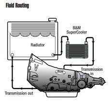
4l60e Transmission Cooler Line Diagram Flow Direction Cpt4l60e The 4l60e is a popular automatic transmission used in many vehicles, and its cooling system plays a vital role in keeping the transmission fluid at the right temperature. fluid flow within the cooler lines starts with the transmission pump, which pushes the transmission fluid through the system. the fluid is then directed towards the. Cooler return line chart chrysler. the transmission 670: top 727 (tf‐8) rear 4l60e: top 4l80e: lower front 4t40 5: bottom 4t40e: lower. From the two diagrams. 1st one looks correct for the 4l60e with a side mount cooler in the cross flow radiator. 2nd one looks like a 4l80e with an auxiliary cooler and a down flow radiator. ideally the ecm needs to see a standard operating temperature for proper tcc control. here's some thing to consider. a) with an auxiliary cooler install. Fluid flow 4l60e transmission cooler lines diagram: fluid transmission line dynamics, 1983 american society of mechanical engineers. winter annual meeting,1983 investigation of dynamic characteristics of fluid transmission lines with flow william r. hammond (1 lt, usaf.),1970 effects of mean flow on the dynamic characteristics of fluid.

Comments are closed.