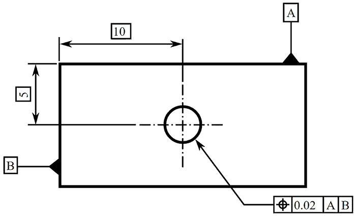
Gd T Basics Understanding Basic Dimensions In Gd T Cnccookbook Be A

Gd T Basics Understanding Basic Dimensions In Gd T Cnccookbook Be A Basic dimensions provide a clear and concise way to communicate design intent, reducing the chances of misinterpretation and manufacturing process errors. by utilizing basic dimensions, engineers can effectively implement gd&t to a part, allowing for more precise control over its size, shape, and position. Gd&t basic concepts. like almost anything else, gd&t basics are simple concepts that we can use to group all of the other information into. we’ll discuss the following key gd&t basics: – gd&t symbols – basic dimensions – feature control frames – datums and features – material condition modifiers.

Gd T Basic Dimensions Ted Youtube Basic dimensions are typically used within the gd&t framework to control the location or geometry of features. the best example of when basic dimensions are used is when specifying true position. take a look at this drawing below: the basic dimensions are those dimensions in the boxes – the 30 and the 15. they do have tolerances, though, as. As basic dimensions are perfect, there would be no deviations, and they would not be recorded on the report. instead of basic dimensions, we would report the following: flatness for datum a. size of the part (60 0.1 for length and width) thickness of the part (16 0.1) size of the holes (Ø12 0.05) position of the holes (cylindrical. Basic rules & philosophy; gd&t datums gd&t datum feature simulators and datum selection gd&t tolerances: plus minus tolerancing gd&t feature control frames gd&t: mmc, lmc, rfs, and bonus tolerances reference charts and tables: gd&t symbols: complete quick reference chart. future chapters (coming soon!): – tolerance stack up analysis – asme. Cnccookbook beginner's guide to gd&t: introduction. geometric dimensioning and tolerancing (gd&t) is a set of standardized symbols and conventions that are used to describe parts in a way that makes it easier for customers, manufacturers, and other supply chain participants to successfully communicate. parts that are manufactured in a shop must.

Gd T Basics Understanding Basic Dimensions In Gd T Cnccookbook Be A Basic rules & philosophy; gd&t datums gd&t datum feature simulators and datum selection gd&t tolerances: plus minus tolerancing gd&t feature control frames gd&t: mmc, lmc, rfs, and bonus tolerances reference charts and tables: gd&t symbols: complete quick reference chart. future chapters (coming soon!): – tolerance stack up analysis – asme. Cnccookbook beginner's guide to gd&t: introduction. geometric dimensioning and tolerancing (gd&t) is a set of standardized symbols and conventions that are used to describe parts in a way that makes it easier for customers, manufacturers, and other supply chain participants to successfully communicate. parts that are manufactured in a shop must. Let's take a more detailed look at each of gd&t's basic concepts. gd&t symbols. the symbols, or geometric symbols, are what most people think of first when they hear about gd&t. there's a collection of symbols that are used to specify each shape characteristic or tolerance that gd&t can describe. here is a typical example, the concentricity. Advantages and disadvantages of gd&t ; gd&t basic concepts. gd&t symbols; basic dimensions; feature control frames; datums; gd&t rules and philosophy. gd&t datums. gd&t datum feature simulators and datum selection. gd&t tolerances: plus minus tolerancing. gd&t: mmc, lmc, rfs, and bonus tolerances. be sure to read over the articles for each.

Comments are closed.