Gd T Symbols Pdf Engineering Tolerance Space

Gd T 101 An Introduction To Geometric Dimensioning And Tolerancing Inc.) in 1995. this center develops and deploys dimensioning and tolerancing best practices within raytheon. as a member of the raytheon learning institute, paul has trained more than 3,500 people in gd&t and mechanical tolerancing in the past 12 years. he has also written numerous articles and design guides on optical and mechanical tolerancing. Unilateral and unequally disposed profile tolerance [asme y14.5 2009 secon 8.3.1.2] to indicate that a profile of a surface tolerance is not symmetrical about the true profile, this symbol is used. the first value in the feature control frame is the total width of the profile tolerance. the value following the symbol is the amount of the tol.

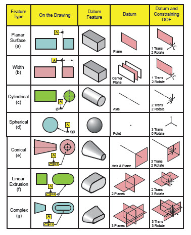
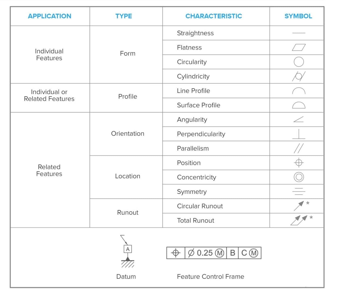
Gd T Symbols Pdf Engineering Tolerance Space Tolerancing for all drawings (castings, machined components,etc.). it is documented in asme y14.5m which has the symbols, rules, and simple examples. also asme y14.8 has guidance for casting and forging drawings. 3 why should gd&t be used? a. it is a simple and effi cient method for describing the tolerancing mandated by the designer of the. Gd&t flatness is a common symbol that references how flat a surface is regardless of any other datum’s or features. it comes in useful if a feature is to be defined on a drawing that needs to be uniformly flat without tightening any other dimensions on the drawing. the flatness tolerance references two parallel planes (parallel to the surface. Gd&t symbols free download as pdf file (.pdf), text file (.txt) or read online for free. geometric dimensioning and tolerancing symbols, rules, and guidelines are provided. key points include: maximum material condition (mmc) and least material condition (lmc) define the amount of material in a feature. geometric tolerances use tolerance. General information about gd&t. at the end of this course, you will be able to meet the objectives outlined below. objectives • define gd&t. • describe the scope of gd&t standards. • distinguish between a feature and a datum. • distinguish between gd&t and traditional tolerancing. • define the datum reference frame (drf).

Gd T Symbols And Guidelines Cheat Sheet Pdf Gd T Symb Vrogue Co Gd&t symbols free download as pdf file (.pdf), text file (.txt) or read online for free. geometric dimensioning and tolerancing symbols, rules, and guidelines are provided. key points include: maximum material condition (mmc) and least material condition (lmc) define the amount of material in a feature. geometric tolerances use tolerance. General information about gd&t. at the end of this course, you will be able to meet the objectives outlined below. objectives • define gd&t. • describe the scope of gd&t standards. • distinguish between a feature and a datum. • distinguish between gd&t and traditional tolerancing. • define the datum reference frame (drf). A feature control frame describes the conditions and tolerances of a geometric control on a part ’s feature. notes: “rfs” means regardless of feature size. it simply means that whatever gd&t callout you make, it is controlled independently of the size dimension of the part. rfs is the default condition of all. The same part that fails with conventional tolerances may pass with gd&t tolerances. the figure below illustrates this issue. notice that a square tolerance zone of .500" will allow a hole center location .707" away from the center if it is located in the squares' corner (diagonally). remembering that a gd&t tolerance value is.

Gd T The Basics Of Geometric Dimensioning And Tolerancing Formlabs A feature control frame describes the conditions and tolerances of a geometric control on a part ’s feature. notes: “rfs” means regardless of feature size. it simply means that whatever gd&t callout you make, it is controlled independently of the size dimension of the part. rfs is the default condition of all. The same part that fails with conventional tolerances may pass with gd&t tolerances. the figure below illustrates this issue. notice that a square tolerance zone of .500" will allow a hole center location .707" away from the center if it is located in the squares' corner (diagonally). remembering that a gd&t tolerance value is.

Comments are closed.