Gen 5 5 3 Engine Cooling System Diagram

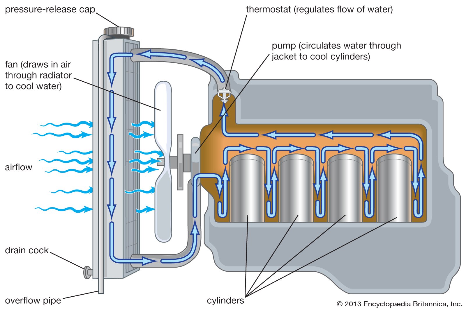
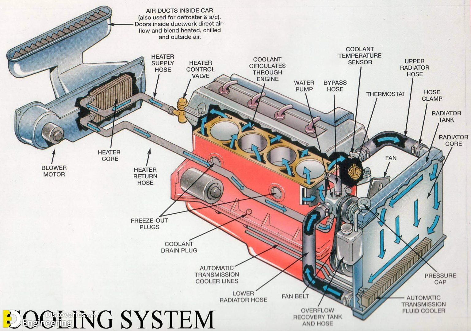
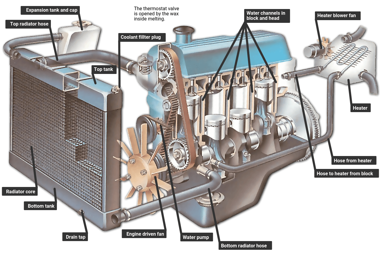
How Engine Cooling System Works Animation At William Farris Blog There are 9 components participating in the 5.3 vortec cooling system. these are the radiator, the upper and lower hose for the radiator, cap or pressure release valve, a water pump, a coolant thermostat, the thermostat housing, and a cooling fan shroud. 5.3 vortec cooling system diagram. the in depth discussion on all parts marked as a, b, c. The cooling system in a 5.3 vortec engine is made up of several different components, all working together to keep your engine at its optimal operating temperature. the main component is the radiator, which transfers heat from the engine coolant to the air outside of the vehicle. the radiator is usually located in front of the engine, where it.

Schematic Diagram Of Engine Cooling System September 7, 2022. the 5.3 vortec cooling system diagram is a helpful tool when it comes to understanding how this type of engine works. the diagram shows all of the different parts of the cooling system and how they are interconnected. it is important to note that the water pump is responsible for circulating coolant throughout the engine. It's important to understand that the lsx motors have what is called a reverse flow cooling system. for years, i thought that meant that the coolant flows in the opposite direction thru the radiator and motor (top to bottom). what it actually means is that the thermostat is at the front door (water pump inlet) of the motor holding the cooler. November 5, 2022. the f 150 ecoboost is a powerful truck that needs a cooling system that can keep up with its engine. the system diagram for the f 150 ecoboost cooling system shows how the different parts of the system work together to keep the engine cool. the radiator is the first part of the system that cools the engine down. Ls and lt engine reference guide for the gen. 3, gen. 4 & gen. 5 ls lt, vortec ecotec3 engines. posted 04 05 18 by onallcylinders staff. last updated on 01 29 2024. introduced in the 2014 c7 corvette, the all new lt engine series is the latest iteration of the gm v8. (image gm corporate newsroom).

Schematic Diagram Of Engine Cooling System November 5, 2022. the f 150 ecoboost is a powerful truck that needs a cooling system that can keep up with its engine. the system diagram for the f 150 ecoboost cooling system shows how the different parts of the system work together to keep the engine cool. the radiator is the first part of the system that cools the engine down. Ls and lt engine reference guide for the gen. 3, gen. 4 & gen. 5 ls lt, vortec ecotec3 engines. posted 04 05 18 by onallcylinders staff. last updated on 01 29 2024. introduced in the 2014 c7 corvette, the all new lt engine series is the latest iteration of the gm v8. (image gm corporate newsroom). The lm7 5.3 vortec engine has aluminum cylinder heads with an iron block and runs on gasoline. it has a 9.5:1 compression ratio and the heads use the ls style cathedral intake ports and oval exhaust ports, with 1.89” intake and 1.55” exhaust valves. the lm7 uses two different camshafts. The ls engine coolant flow diagram is an essential part of understanding how the cooling system in an ls engine works. this diagram shows the path that coolant takes through the engine, from the radiator to the water pump and back again. understanding this flow is crucial for diagnosing any cooling system problems and ensuring that the engine.

How Engine Cooling System Works Engineering Discoveries The lm7 5.3 vortec engine has aluminum cylinder heads with an iron block and runs on gasoline. it has a 9.5:1 compression ratio and the heads use the ls style cathedral intake ports and oval exhaust ports, with 1.89” intake and 1.55” exhaust valves. the lm7 uses two different camshafts. The ls engine coolant flow diagram is an essential part of understanding how the cooling system in an ls engine works. this diagram shows the path that coolant takes through the engine, from the radiator to the water pump and back again. understanding this flow is crucial for diagnosing any cooling system problems and ensuring that the engine.

How An Engine Cooling System Works How A Car Works

Comments are closed.