Geometrical Tolerances

Gd T 101 An Introduction To Geometric Dimensioning And Tolerancing Learn about the system for defining and communicating engineering tolerances via a symbolic language on drawings and 3d models. find out the origin, fundamental concepts, rules, and standards of gd&t. Learn about the symbols and concepts of geometric dimensioning and tolerancing (gd&t) with this comprehensive guide. find definitions, examples, and downloadable wall chart for easy reference.

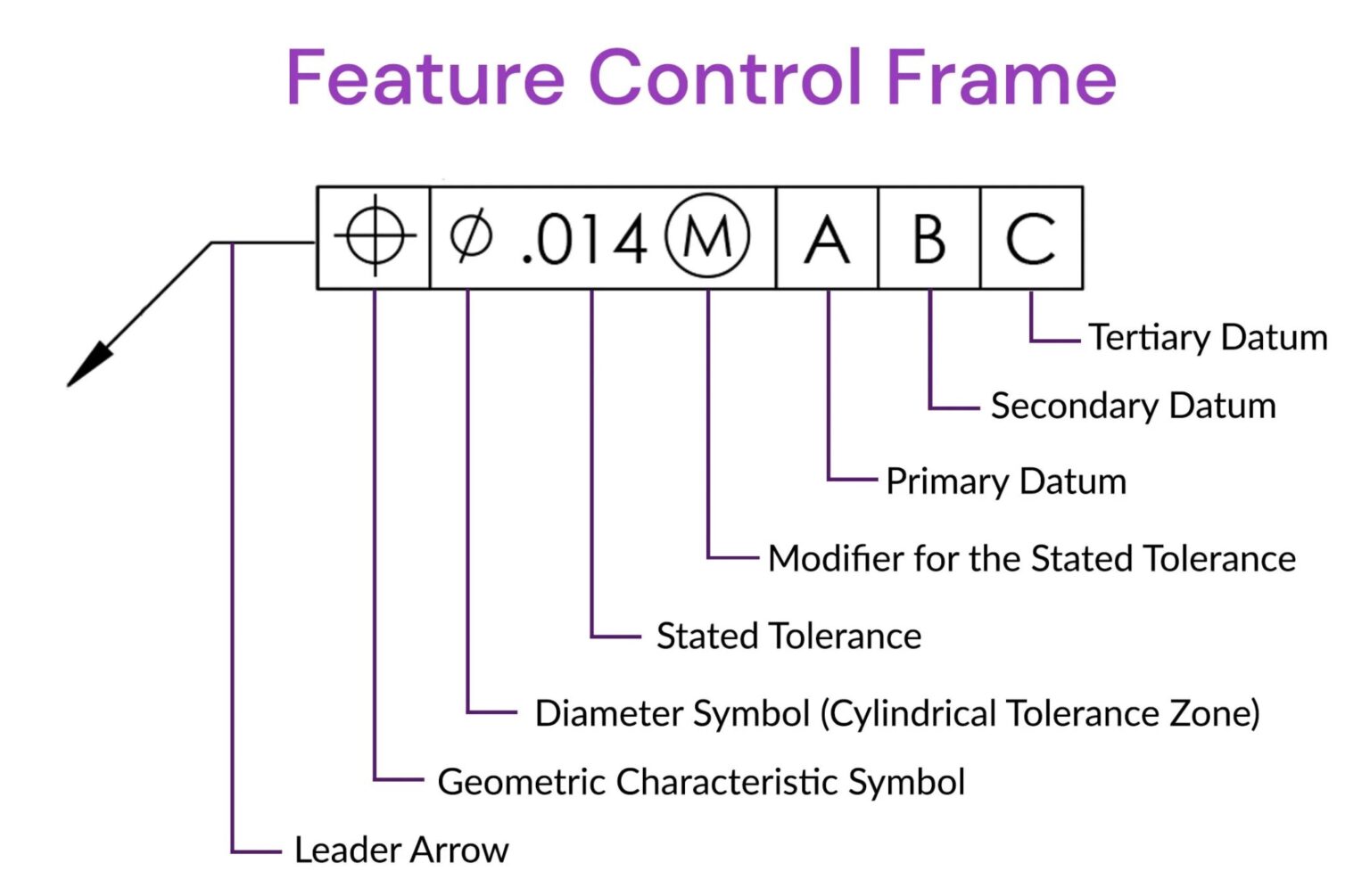
What Are Geometric Dimensioning And Tolerancing Gd T Symbols With the dimension scheme completed, add individual geometric tolerances and gd&t symbols. the software automatically generates dimensions for features of size (fos), such as holes and bosses. make sure to select ‘bilateral’ or ‘limit’ as tolerance type for features where the plus and minus limit are unequal. Learn about the types, symbols, and applications of geometric tolerances in mechanical engineering. this blog post explains the basic terminology, examples, and tips for achieving precision and accuracy in manufacturing. Time to read: 14 min. this article was originally published in february, 2017 by jeremy hill.the content has been updated. geometric dimensioning and tolerancing (gd&t or gd and t) is a language of symbols and standards designed and used by engineers and manufacturers to describe the shape (geometry) and size (dimensions) of a product and facilitate communication between entities working. Gd&t is a set of rules and symbols used on a drawing to communicate the intent of a design, focusing on the function of the part. learn the history, benefits, and basics of gd&t, and how to apply it to size, location, orientation, and form.

Engr1304 Chapter 7 Tolerances Time to read: 14 min. this article was originally published in february, 2017 by jeremy hill.the content has been updated. geometric dimensioning and tolerancing (gd&t or gd and t) is a language of symbols and standards designed and used by engineers and manufacturers to describe the shape (geometry) and size (dimensions) of a product and facilitate communication between entities working. Gd&t is a set of rules and symbols used on a drawing to communicate the intent of a design, focusing on the function of the part. learn the history, benefits, and basics of gd&t, and how to apply it to size, location, orientation, and form. Learn how to use gd&t, a system of symbols and standards to specify the form, size, orientation, and location of parts and features. find out the types and examples of form, profile, and orientation tolerances, and how they are defined by asme y14.5. The asme website describes the y14.5 standard as follows: “the y14.5 standard is considered the authoritative guideline for the design language of geometric dimensioning and tolerancing (gd&t.) it establishes symbols, rules, definitions, requirements, defaults, and recommended practices for stating and interpreting gd&t and related.

Comments are closed.