Heating And Cooling Wiring Diagram

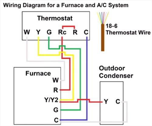
Heating And Cooling Thermostat Wiring Diagram Collection R or rc wire (power) connected to the r power terminal to power the thermostat. w wire (heat), connected to the heating control. g wire (fan) connected to the fan control to operate a blower in your hvac system. y1 wire (cooling) connected to the y terminal compressor refrigerant system. Many types of systems can. a heat pump with 2 stages of heating and cooling, a system with aux heating or one that has a reversing valve that needs to be energized. how to wire a 7 wire thermostat: 1). attach the red wire to the r terminal for 24v power. 2). attach the white wire to the w (or w1) terminal for the heat pump’s heating mode. 3).

Thermostat Wiring To A Furnace And Ac Unit Color Code How It Works The hvac wiring diagram thermostat illustrates the electrical connections between the thermostat, the heating or cooling system, and the power supply. it shows the different wires and terminals involved in the system and their corresponding functions. the diagram provides a visual representation of how the thermostat interacts with the hvac. An hvac wiring diagram is a visual representation of the electrical components and their connections in a heating, ventilation, and air conditioning system. it is an essential tool for understanding and troubleshooting the electrical system of an hvac system. the diagram illustrates the flow of electrical current and provides a detailed. Air conditioner thermostat wiring details and color code. r terminal is connected to the red wire or r wire this is 24 volt power for the thermostat and controlled devices. origin is the control transformer and then the r terminal. g terminal is connected to the green wire or g wire this is for the blower fan in the air handler. Learn how to wire your thermostat with this step by step guide from honeywell home. see the diagram and instructions for different wiring configurations and system types.

Heating And Cooling Thermostat Wiring Diagram Air conditioner thermostat wiring details and color code. r terminal is connected to the red wire or r wire this is 24 volt power for the thermostat and controlled devices. origin is the control transformer and then the r terminal. g terminal is connected to the green wire or g wire this is for the blower fan in the air handler. Learn how to wire your thermostat with this step by step guide from honeywell home. see the diagram and instructions for different wiring configurations and system types. Key wires: red (r) for power, white (w) for heating, and yellow (y) for cooling. process: connect the red wire to the r terminal, the white wire to the w terminal, and the yellow wire to the y terminal. if there’s a green wire for the fan, connect it to the g terminal. programmable thermostats:. In the hvac (heating, ventilation, and air conditioning) industry, understanding wiring diagrams is crucial for technicians and installers. these diagrams provide a visual representation of the electrical connections and components involved in an hvac system, allowing professionals to troubleshoot and repair any issues effectively.

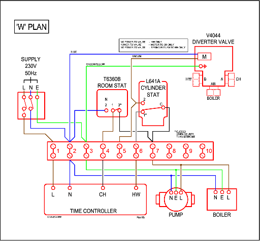
Wiring Diagram For S Plan Central Heating System Wiring Diagram Key wires: red (r) for power, white (w) for heating, and yellow (y) for cooling. process: connect the red wire to the r terminal, the white wire to the w terminal, and the yellow wire to the y terminal. if there’s a green wire for the fan, connect it to the g terminal. programmable thermostats:. In the hvac (heating, ventilation, and air conditioning) industry, understanding wiring diagrams is crucial for technicians and installers. these diagrams provide a visual representation of the electrical connections and components involved in an hvac system, allowing professionals to troubleshoot and repair any issues effectively.

Heating And Cooling Thermostat Wiring Diagram

Comments are closed.