Homemade Circuit Projects Make This Simple Fm Radio Circuit Using A

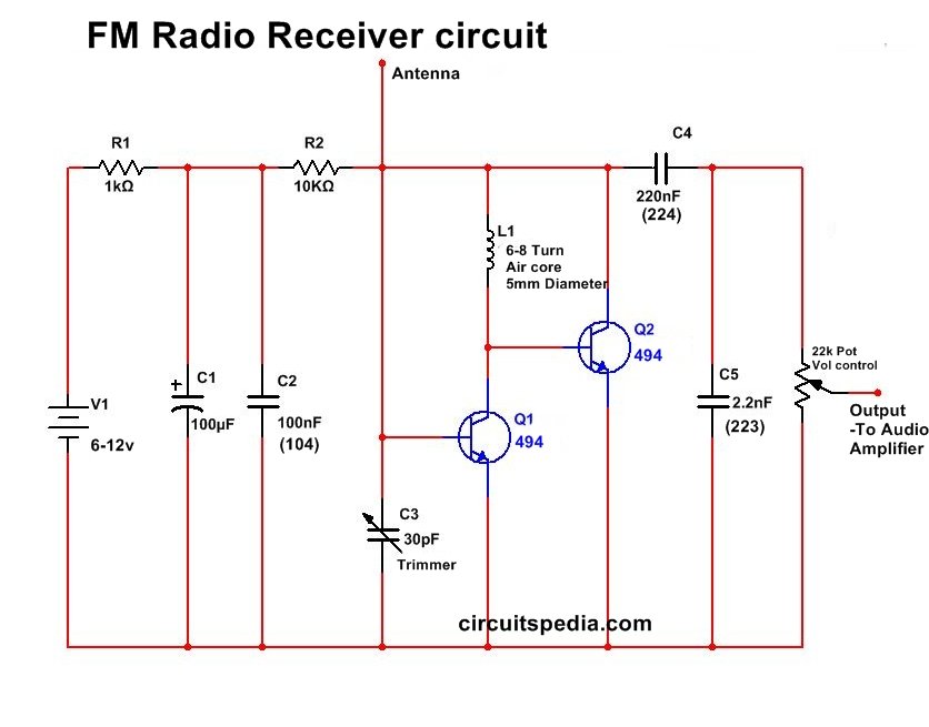
Homemade Circuit Projects Make This Simple Fm Radio Circuit Using A R1 = 1k 1 4 watt 5% resistor. earphone (magnetic) this is a fascinating small single transistor fm receiver that, unbelievably, can tune the full 88 108 mhz fm music band while still producing enough energy to power a typical set of magnetic earbuds. the tiny receiver is so small that it could be integrated into an empty cigarette pack. Simple high performance mw receiver circuit. an improved version of the above medium wave radio can be studied in the following paragraphs. once built it can be expected to work immediately without any hassles. the mw receiver works with four transistors. the first transistor is configured to work in the reflex mode.

How To Make Fm Transmitter Circuit With 3 Km Range Potentiometer p1 should subsequently be adjusted to allow the ideal fm reception of the transmitter. when integrated with a loudspeaker and an amplifier (for example an lm386 amplifier), this simple fm radio circuit could very easily be constructed into a extremely sleek and stylish pocket radio. circuit diagram. test point voltages. 3.4 v. 0.2 v. The tda7000 is a monolithic integrated circuit for mono fm portable radios, where a minimum on peripheral components is crucial. the ic tda 7000 has a frequency locked loop system with an intermediate frequency of 70 khz. the intermediate frequency selectivity is achieved by active rc filters. the only function which needs alignment is the. Poc video tutorial in hindi: the fm receiver is capable of receiving 76 to 108mhz fm band with stereo output having good sensitivity and performance. the output is capable of driving a 32Ω speaker directly, which eliminates additional audio headphone amplifiers. advertisement . the heart of the circuit is based on ic hex3653 gs1299 rda7088. Fm receiver circuit explanation. here’s a simple fm receiver circuit with minimum components for local fm reception. transistor bf495 (t2), together with a 10k resistor (r1), coil l, 22pf variable capacitor (vc), and internal capacitances of transistor bf494 (t1), comprises the colpitts oscillator. trimmer vc sets the resonance frequency of.

How To Make A Simple Radio Receiver Poc video tutorial in hindi: the fm receiver is capable of receiving 76 to 108mhz fm band with stereo output having good sensitivity and performance. the output is capable of driving a 32Ω speaker directly, which eliminates additional audio headphone amplifiers. advertisement . the heart of the circuit is based on ic hex3653 gs1299 rda7088. Fm receiver circuit explanation. here’s a simple fm receiver circuit with minimum components for local fm reception. transistor bf495 (t2), together with a 10k resistor (r1), coil l, 22pf variable capacitor (vc), and internal capacitances of transistor bf494 (t1), comprises the colpitts oscillator. trimmer vc sets the resonance frequency of. The above shown wireless fm transmitter circuit is basically a small rf transmitter built around a single transistor. the circuit functions quite like a colpitts oscillator incorporating a tank circuit for the generation of the required oscillations. the frequency mainly depends on the positioning and the values of the inductor, c1, c2 and c3. When the frequency is modulated between low and high, music or voice is being transmitted by the carrier frequency. but only the frequency changes as a result; the amplitude remains constant the entire time. fm radio operates in the range of 87.5 mhz to 108.0 mhz. find out more about working of fm radio. fm radio pcb layout: top view:.

Very Simple Fm Radio Receiver Circuit Circuitspedia The above shown wireless fm transmitter circuit is basically a small rf transmitter built around a single transistor. the circuit functions quite like a colpitts oscillator incorporating a tank circuit for the generation of the required oscillations. the frequency mainly depends on the positioning and the values of the inductor, c1, c2 and c3. When the frequency is modulated between low and high, music or voice is being transmitted by the carrier frequency. but only the frequency changes as a result; the amplitude remains constant the entire time. fm radio operates in the range of 87.5 mhz to 108.0 mhz. find out more about working of fm radio. fm radio pcb layout: top view:.

Comments are closed.