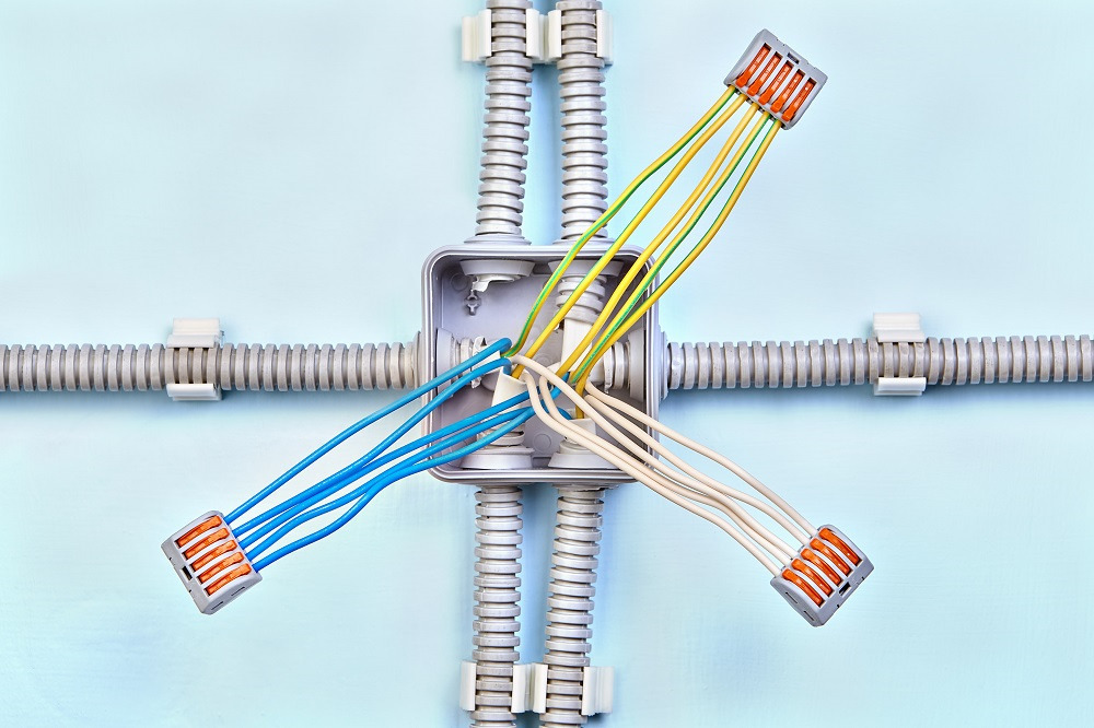
How To Connect Wires To A Junction Box Wiring Diagram And Schematics

Junction Box Electrical Wiring Diagrams Start by identifying the power source, typically a breaker panel or switch. from there, trace the circuit to the junction box, noting the incoming and outgoing cables, as well as any connections made within the box. this diagram will serve as a reference for future work on the circuit. troubleshooting and maintenance. The next thing you’ll need is a wiring diagram for your telephone junction box. this diagram will show you how to correctly connect all the components of the system. a good diagram should include information about the color of each wire, which terminal it connects to, and any important notes about the correct way to wire the system. once you.

Junction Boxes Light Wiring Illustrations on how to wire switches and lights using junction box. Make sure you screw each terminal screw down nice and tight. step 4 – fix and screw cap on: once all connected up, screw the junction box to a nearby joist or rafter or similar and then screw the cap back on. step 5 – test: once all secured, turn the power back on and then test the installation. Consider the layout of the wiring and the length of the wires to ensure they can reach the box comfortably. 4. cut the hole: use a power drill and the appropriate sized hole saw bit to cut a hole in the wall or ceiling for the junction box. Step 3: connect the traveler wire. the traveler wire is used to transfer the electrical current between the two switches. in a 3 way wiring setup, the traveler wire is connected to the traveler terminals on both switches and the traveler terminal on the junction box. again, use wire connectors to ensure a secure connection.

How To Connect Wires To A Junction Box Wiring Diagram And Schematics Consider the layout of the wiring and the length of the wires to ensure they can reach the box comfortably. 4. cut the hole: use a power drill and the appropriate sized hole saw bit to cut a hole in the wall or ceiling for the junction box. Step 3: connect the traveler wire. the traveler wire is used to transfer the electrical current between the two switches. in a 3 way wiring setup, the traveler wire is connected to the traveler terminals on both switches and the traveler terminal on the junction box. again, use wire connectors to ensure a secure connection. Step 4: connect wires to terminals. connect the stripped ends of the wires to the appropriate terminals inside the junction box. follow the wiring diagram or standard electrical practices to ensure correct connections. it is important to securely tighten the terminal screws to create a reliable electrical connection. Fasten the cable using a wire staple within 12 inches (30 cm) of the box to secure it. for junction boxes installed on the ceiling, run the cable from the ceiling down into the box. 3. strip the wires with wire strippers. start with one wire and strip off 3⁄4 inch (19 mm) of casing insulation at the end.

Comments are closed.