How To Read And Understand A Schematic

How To Read A Schematic Sparkfun Learn An electrical schematic is a diagram that shows how all of the wires and components in an electronic circuit are connected. they’re like a map for building or troubleshooting circuits, and can tell you almost everything you need to know to understand how a circuit works. the ability to read electrical schematics is a really useful skill to have. Reading schematics. understanding which components are which on a schematic is more than half the battle towards comprehending it. now all that remains is identifying how all of the symbols are connected together. nets, nodes and labels. schematic nets tell you how components are wired together in a circuit.

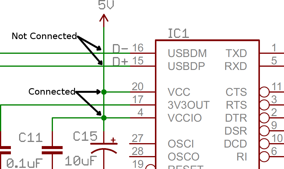
How To Read And Understand A Schematic An electrical schematic is a graphical representation of an electrical circuit. it shows the connections and components of the circuit in a clear and concise manner. understanding the key components of an electrical schematic is essential for anyone working with electrical systems. 1. symbols: one of the most important elements of an electrical. Electrical loads might be difficult to identify in complex schematics. try looking up pictures of simple electrical loads to get the basic idea. 4. identify resistors, note that resistors are marked by a zig zag line or rectangle. scan over your schematics and look for any distinct blocks or angled lines in the plans. Anyone can take an idea this far, but the next step requires a fundamental understanding of circuit schematics. circuit schematics are the bridge between conceptual electrical design and physical realization of a printed circuit board assembly, or pcba. example circuit schematic: class a common base small signal high gain amplifier. Circuit diagram connections. circuit diagrams or schematic diagrams show electrical connections of wires or conductors by using a node as shown in the image below. a node is simply a filled circle or dot. when three or more lines touch each other or cross each other and a node is placed at the intersection, this represents the lines or wires.

How To Read And Understand A Schematic Anyone can take an idea this far, but the next step requires a fundamental understanding of circuit schematics. circuit schematics are the bridge between conceptual electrical design and physical realization of a printed circuit board assembly, or pcba. example circuit schematic: class a common base small signal high gain amplifier. Circuit diagram connections. circuit diagrams or schematic diagrams show electrical connections of wires or conductors by using a node as shown in the image below. a node is simply a filled circle or dot. when three or more lines touch each other or cross each other and a node is placed at the intersection, this represents the lines or wires. An electrical schematic is a graphical representation of an electrical circuit, using standardized symbols to depict components and their connections. schematics convey the circuit's design and function, making it easier to understand how it operates. symbols are the foundation of circuit diagrams, enabling engineers, electricians, and. A schematic, also known as a circuit diagram, is a visual representation of an electronic circuit. it uses standardized symbols to represent electronic components and shows how these components are connected to form a circuit. unlike a pictorial diagram, a schematic doesn’t aim to represent the physical layout of the components.

Beginners Guide How To Read Electrical Schematics Images An electrical schematic is a graphical representation of an electrical circuit, using standardized symbols to depict components and their connections. schematics convey the circuit's design and function, making it easier to understand how it operates. symbols are the foundation of circuit diagrams, enabling engineers, electricians, and. A schematic, also known as a circuit diagram, is a visual representation of an electronic circuit. it uses standardized symbols to represent electronic components and shows how these components are connected to form a circuit. unlike a pictorial diagram, a schematic doesn’t aim to represent the physical layout of the components.

How To Read Electronic Schematic Diagrams

Comments are closed.