Lab5 Pdf Lab 5 Seven Segment Display Driver The Goal Of This Lab Is

Lab5 Pdf Lab 5 Seven Segment Display Driver The Goal Of This Lab Is View lab5.pdf from ece 3300l at california polytechnic state university, pomona. lab 5 seven segment display driver the goal of this lab is to build a complete seven segment display driver, which. Lab 5 5, page 1. study the safety policy statement (toyota electricity 102) objectives: upon completion of this lab you should be able to: • explain how a seven segment display functions • read the truthtables of a seven segment display • wire a seven segment decoder driver to a plc • program the plc for a 7 segment decoder driver.

Lab5 Handout Eel3701c 编程辅导, code help, wechat: powcoder, cs tutor, powcoder@163 eel3701c lab 5 lab5.pdf at main · powcoder eel3701c lab 5. The 7447 ic is a bcd to 7 segment decoder driver that has 4 inputs for the bcd digit. input d is the most significant and input a is the least significant. the 4 bit bcd digit is converted to a 7 segment code with outputs a through g. the outputs of the 7447 are applied to the inputs of the seven segment display. this ic contains the 7 led. When implemented correctly, your circuit will display value of the input as a hexadecimal digit on the 7 segment display. below is the display with each segment labeled. your display controller should pass its 4 inputs to the 4 16 decoder you constructed and the output of the decoder should be used to drive the seven led signals. 2 prelab in this lab, you will be redesigning your 7 segment display driver from the previous parts of lab 5 using hdl code and a pld. this will require your truth table, k maps, reduced expressions, and your wincupl code. most of this you will already have from lab 5 1. the wincupl code will need to be written before the lab. 1 cpen 3700 lab 5 3.

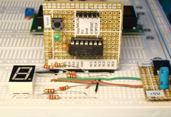
Lab5 Pdf Course Hero When implemented correctly, your circuit will display value of the input as a hexadecimal digit on the 7 segment display. below is the display with each segment labeled. your display controller should pass its 4 inputs to the 4 16 decoder you constructed and the output of the decoder should be used to drive the seven led signals. 2 prelab in this lab, you will be redesigning your 7 segment display driver from the previous parts of lab 5 using hdl code and a pld. this will require your truth table, k maps, reduced expressions, and your wincupl code. most of this you will already have from lab 5 1. the wincupl code will need to be written before the lab. 1 cpen 3700 lab 5 3. Breadboard implementation of the 7 segment led display circuit. the bcd inputs are designated a, b, c, and d in order from least significant to most significant. the truth table for mapping these bcd inputs to the seven segment outputs is provided in table 1. table 1. a truth table for 4511 ic bcd to 7 segment display driver. Assigned task – seven segment display in the class notes we presented a seven segment display driver. rtl code for that seven segment display is given below. enter the code into a new project in quartus ii. then, create a new module that instantiates the seg7 code twice – one taking an input from sw3 –.

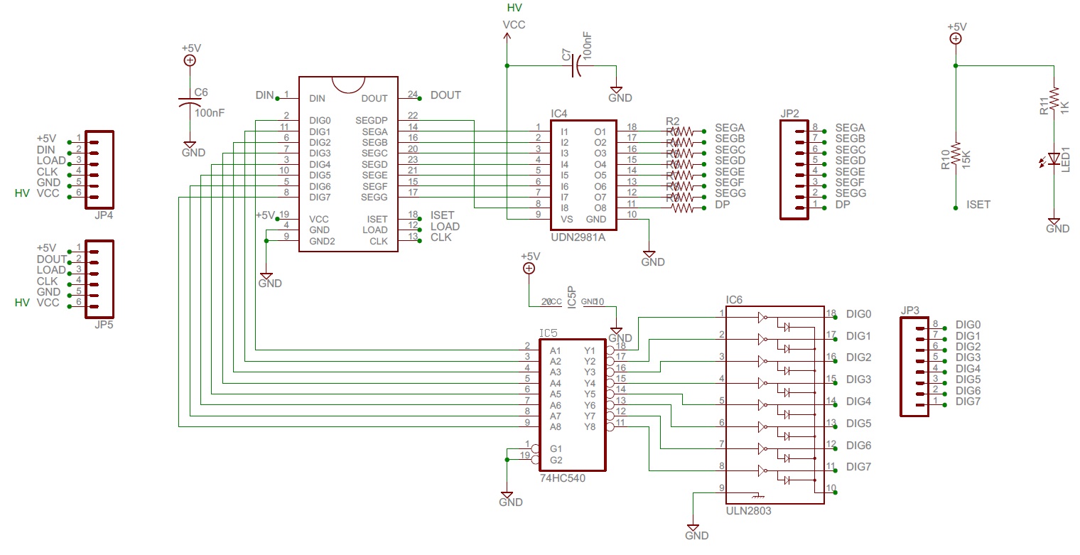
High Voltage Seven Segment Led Display Driver With Spi Interface Breadboard implementation of the 7 segment led display circuit. the bcd inputs are designated a, b, c, and d in order from least significant to most significant. the truth table for mapping these bcd inputs to the seven segment outputs is provided in table 1. table 1. a truth table for 4511 ic bcd to 7 segment display driver. Assigned task – seven segment display in the class notes we presented a seven segment display driver. rtl code for that seven segment display is given below. enter the code into a new project in quartus ii. then, create a new module that instantiates the seg7 code twice – one taking an input from sw3 –.

Img Pic16f688 Lab5 Setup Embedded Lab

Comments are closed.