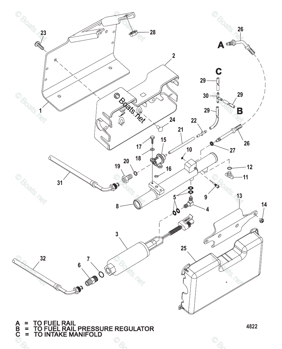
Mercruiser Cool Fuel Diagram

Mercruiser Inboard Gas Engines Oem Parts Diagram For Cool Fuel System 6. install the supplied hose clamps on the large cooling hoses and attach to the new orifice meter assembly, if replacing. 7. install the supplied hose clamps on the water hoses of the orifice meter assembly and connect the hoses to the inlet and outlet barbed fittings on the gen iii cool fuel module. 8. Allow the engine to cool completely and release all fuel servicing any part of the fuel system. always protect eyes and skin from pressurized fuel and vapors. remove and retain the engine cover. disconnect the negative (–) battery cable from the battery. disconnect the positive ( ) battery cable from the battery.

Mercruiser Sterndrive Gas Engines Oem Parts Diagram For Cool Fuel 0210 and belownote: engines equipped with the gen ii cool fuel system are not affected. situationa new gen iii cool fuel module is being introduced to replace the existing gen iii module. ngines with serial numbers above the range listed are equipped with the new module from the factory. the prim. ry difference between the designs is the method. Summary of contents for mercury mercruiser. page 1 service manual #40 gen iii cool fuel supplement to #30 & 31 page 2 it may also be used to alert against unsafe practices. this manual has been written and published by the service department of mercury marine to aid our dealers’ mechanics and company service personnel when servicing the. 7) unbolt the pump from the motor mount. it is held in place with 2 nuts, 9 16" hex heads. 8) drag the whole apparatus, fuel lines and fuel filter out of the boat. 9) remove the pump and cooler assembly from the housing making sure to not get any white heat dissipating grease on your skin, it burns like bad things. High pressure fuel pump. p isolator outlet sealnote: fuel inlet seal for low‐pressure pump may not come out with the pump when pump is removed from. the cool fuel module housing. be sure to remove the seal from the housing before low‐pr. ss. re fuel pump installation.9. drain fuel from gen iii cool fuel modu.

Comments are closed.