Mercruiser Cooling System Flow Chart

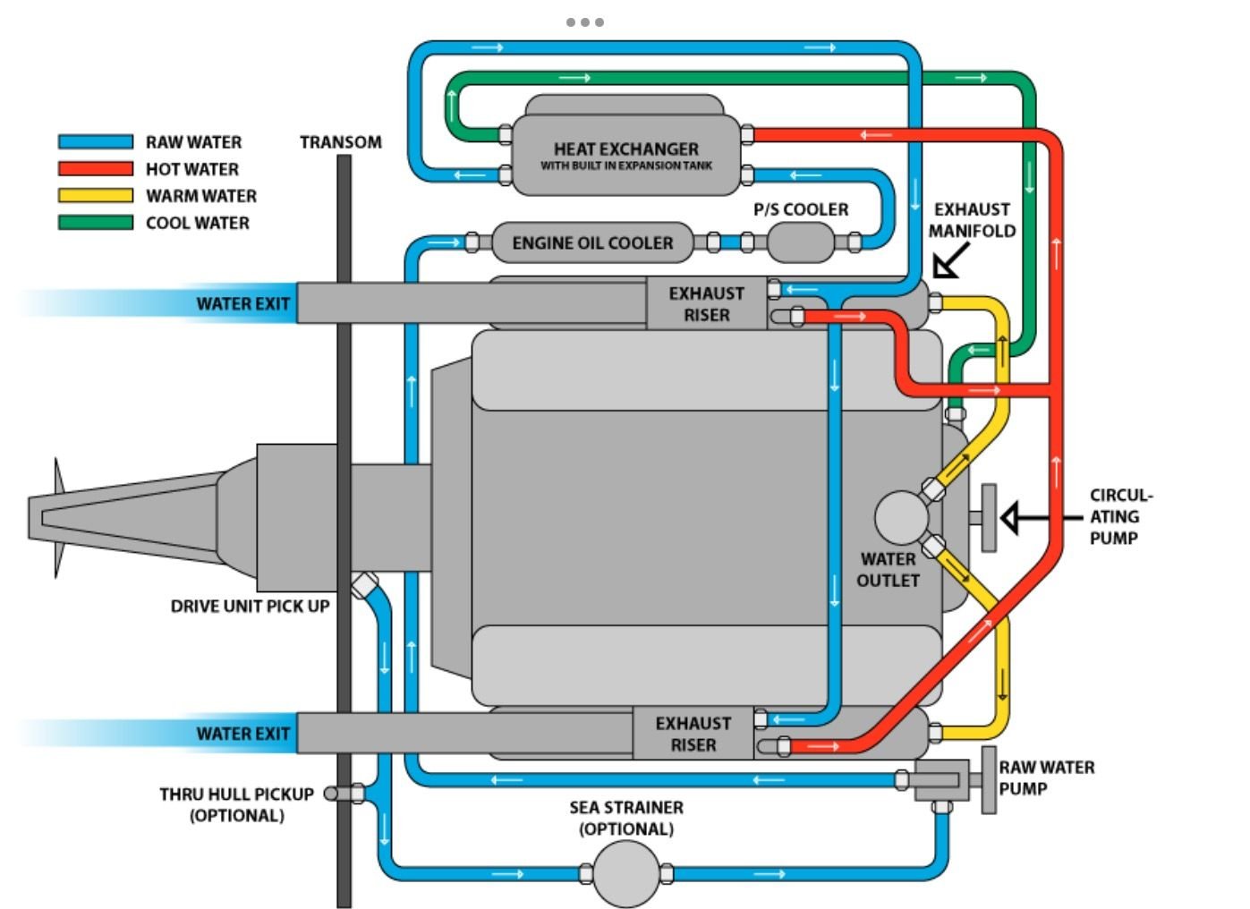
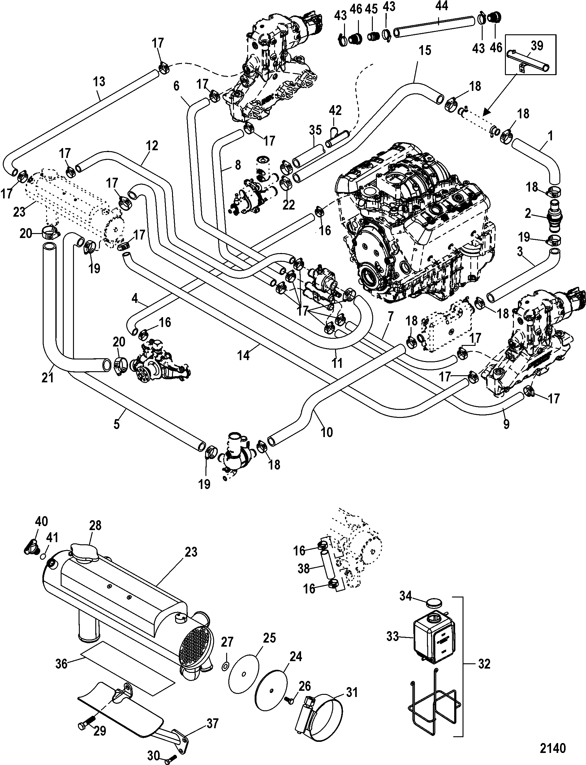
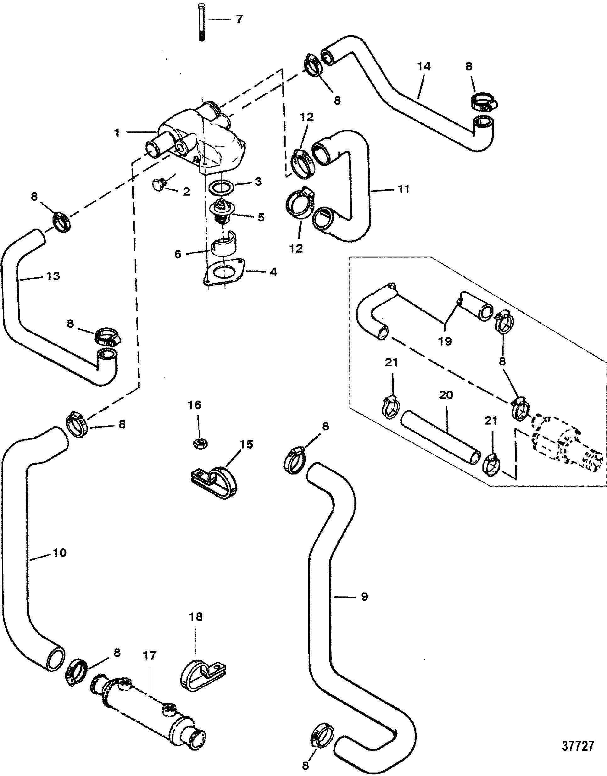
Mercruiser 470 Fresh Water Cooling System Diagram вђ Theme Route The cooling system in your mercruiser engine plays a critical role in its operation. it prevents the engine from overheating, which can cause severe damage and reduce engine life. by maintaining an optimal temperature, the cooling system ensures your engine runs efficiently. this leads to better fuel economy, improved performance, and less wear. Learn how the cooling system works in mercruiser marine engines and what components are involved. see the schematic diagram and explanations of the water pump, thermostat, heat exchanger, and more.

Mercruiser Cooling System Flow Chart Learn how the mercruiser closed cooling system works to regulate the engine temperature and prevent overheating. see the diagram and the key components, such as heat exchanger, coolant reservoir, thermostat, and circulating pump. Cooling flow diagram: therefore referencing the above flow diagram we want to point out a few of the following mercruiser specific features: reference item “c” check valve – this is a patented feature offered by mercruiser. since mercruiser offers the easy to use single point drain system’s they have to take into account that. The cooling system in the mercruiser 350 mag is designed to regulate the engine’s operating temperature and prevent overheating. it consists of several key components, including the engine block, water pump, thermostat, heat exchanger, and raw water cooling system. each of these components plays a vital role in the overall cooling process. Mercruiser engines, known for their reliability and power, are no exception. one crucial aspect of maintaining an engine’s performance and longevity is its cooling system. closed cooling systems have become the go to solution for many mercruiser engine owners, offering a range of benefits from increased efficiency to reduced corrosion.

Mercruiser Cooling System Flow Chart A Visual Reference Of Charts The cooling system in the mercruiser 350 mag is designed to regulate the engine’s operating temperature and prevent overheating. it consists of several key components, including the engine block, water pump, thermostat, heat exchanger, and raw water cooling system. each of these components plays a vital role in the overall cooling process. Mercruiser engines, known for their reliability and power, are no exception. one crucial aspect of maintaining an engine’s performance and longevity is its cooling system. closed cooling systems have become the go to solution for many mercruiser engine owners, offering a range of benefits from increased efficiency to reduced corrosion. In this video i describe how water flows through a single point drain system on a mercruiser 5.0 mpfi marine engine. it’s so complicated that i had to docume. Step 2: flush the cooling system. connect the flush kit to the water inlet on the side of your mercruiser engine. turn on the water supply and start the engine. let the engine run for around 10 minutes to flush out any salt, sand, or debris that may be trapped in the cooling system. step 3: drain the cooling system.

Mercruiser Cooling System Flow Chart A Visual Reference Of Charts In this video i describe how water flows through a single point drain system on a mercruiser 5.0 mpfi marine engine. it’s so complicated that i had to docume. Step 2: flush the cooling system. connect the flush kit to the water inlet on the side of your mercruiser engine. turn on the water supply and start the engine. let the engine run for around 10 minutes to flush out any salt, sand, or debris that may be trapped in the cooling system. step 3: drain the cooling system.

Comments are closed.