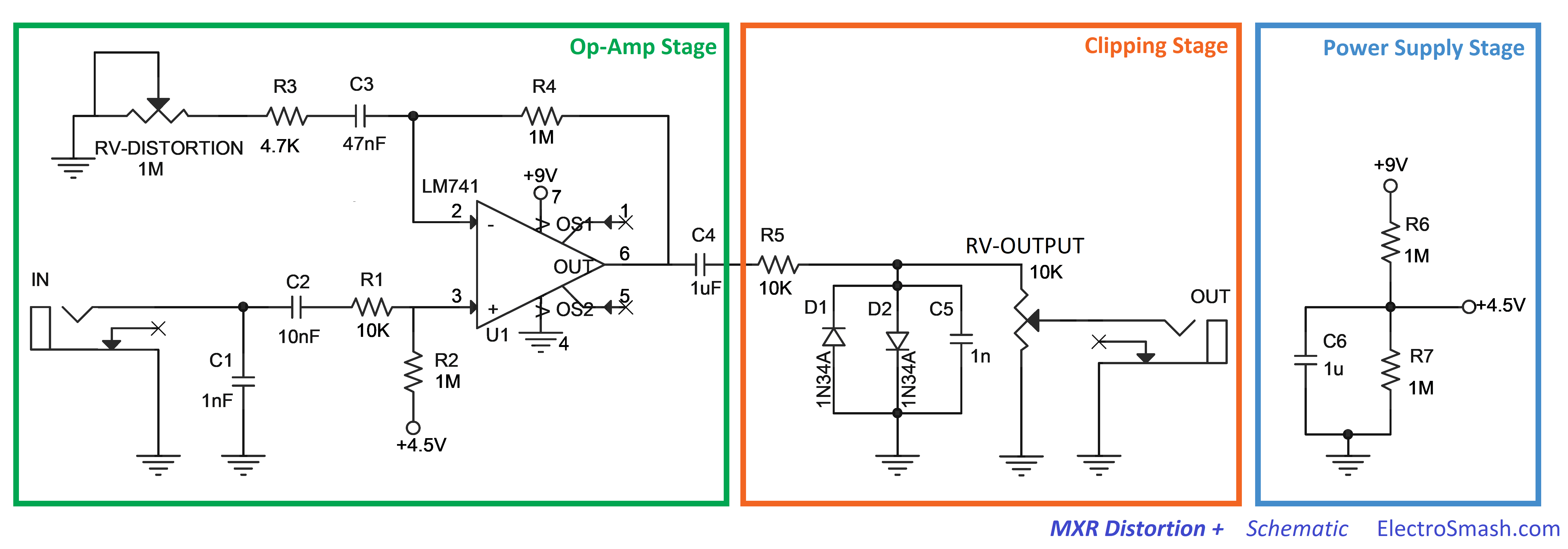
Mxr Distortion Plus Schematic

Building Mxr Distortion Plus Barbarach Bc Learn how the mxr distortion pedal creates a mild fuzzy distortion with germanium diodes and a simple op amp design. see the schematic, frequency response, sound signature and resources of this classic guitar effect. The m 104 mxr distortion , also known as the distortion plus or d is a guitar pedal that mxr designed and released between 1978 and 1979. when it first came out, the original pedal didn't have an external power jack or an indicator led. jim dunlop acquired the mxr licensing rights and now make reissues of this classic mxr distortion pedal and.

Dirtbox Layouts Mxr Distortion Plus Mxr distortion plus schematic (click for full size image) the schematic did not have details of the pot’s tapers. output pot is easy – so far it has always been audio taper to control level or volume or, in this case output (whatever the label). Mxr™ distortion plus™. the distortion plus pedal is very popular and good sounding distortion. it is strikingly similar to the dod overdrive 250 distortion pedal. this project uses the same ready for transfer printed circuit board layout file that is used in the dod 250 overdrive project on this site. general build instructions. Myxr distortion circuit schematic (click for full image) the difference from the one used in breadboarding is u1 – i used tl072. in the breadboarding video i tried it out along with lm741, sounded pretty similar. since i changed the op amp i added c7 (47p) to make the output response near identical. The aphelion distortion project is a clone of the mxr distortion and dod 250 overdrive, which are essentially the same circuit with a few different values. the distortion first came out in 1973 and the dod 250 followed in 1976. other later variants include the mxr microamp and the dod yjm308. this was one of the first circuits to use hard.

Electrosmash Mxr Distortion Circuit Analysis Myxr distortion circuit schematic (click for full image) the difference from the one used in breadboarding is u1 – i used tl072. in the breadboarding video i tried it out along with lm741, sounded pretty similar. since i changed the op amp i added c7 (47p) to make the output response near identical. The aphelion distortion project is a clone of the mxr distortion and dod 250 overdrive, which are essentially the same circuit with a few different values. the distortion first came out in 1973 and the dod 250 followed in 1976. other later variants include the mxr microamp and the dod yjm308. this was one of the first circuits to use hard. The mxr distortion uses a pair of germanium diodes in an asymmetrical configuration, allowing for a smooth and responsive distortion effect. aside from the op amp and diodes, the mxr distortion also features various other components that shape its sound. these include resistors, capacitors, and potentiometers. The first truly successful distortion pedal was the 1973 "distortion " by the mxr company. this fireball, and the phase 90 stomp box, were the starting points of this then very young firm that would become very successful over the following years. the 9 volt operated distortion sports two knobs and is in fact of quite simple build, requiring.

Electrosmash Mxr Distortion Circuit Analysis The mxr distortion uses a pair of germanium diodes in an asymmetrical configuration, allowing for a smooth and responsive distortion effect. aside from the op amp and diodes, the mxr distortion also features various other components that shape its sound. these include resistors, capacitors, and potentiometers. The first truly successful distortion pedal was the 1973 "distortion " by the mxr company. this fireball, and the phase 90 stomp box, were the starting points of this then very young firm that would become very successful over the following years. the 9 volt operated distortion sports two knobs and is in fact of quite simple build, requiring.

Comments are closed.