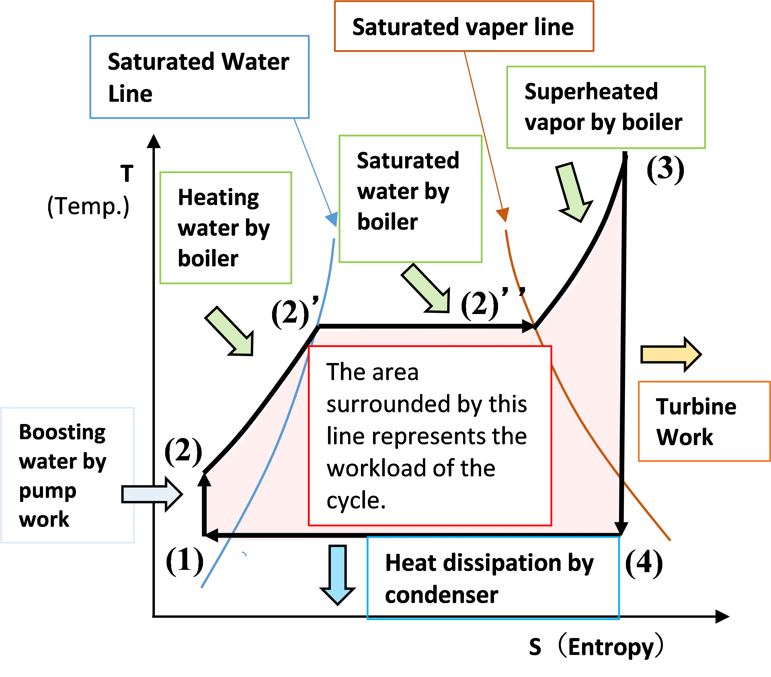
P H And T S Diagram Of Rankine Cycle

Rankine Cycle Ideal Rankine Cycle Efficiency Mechanicaltutorial Rankine cycle is explained along with t s, p v, diagrams, reheat, equation, etc. all the formulas and examples are well captured to have a basic idea. this is basic thermodynamic cycle on which heat engine works and it helps to extract heat from a fluid between a heat source and sink. Figure 1 shows the idealized rankine cycle. the pressure enthalpy (p h) and temperature entropy (t s) diagrams of this cycle are given in figure 2. the rankine cycle operates in the following steps: 1 2 3 isobaric heat transfer. high pressure liquid enters the boiler from the feed pump (1) and is heated to the saturation temperature (2).

Explaining Rankine Cycle In An Easy Explain Steam Engineering In An Rankine cycle. the rankine cycle is a modified form of carnot cycle, in which the isothermal compression (3 4) is continued unit the steam is condensed into water. a carnot cycle, using steam as a working substance, is represented or p v and t s diagram as shown in the figure. consider 1kg of water at pressure p1 and absolute temperature t1 as. T–s diagram of a typical rankine cycle operating between pressures of 0.06 bar and 50 bar. left from the bell shaped curve is liquid, right from it is gas, and under it is saturated liquid–vapour equilibrium. there are four processes in the rankine cycle. the states are identified by numbers (in brown) in the t–s diagram. Rankine cycle definition: the rankine cycle is used in power plants to convert steam into mechanical energy using turbines, boilers, condensers, and pumps. ideal rankine cycle: involves isentropic processes with no losses, represented in p h and t s diagrams. actual rankine cycle: includes real world inefficiencies like friction and heat loss. The schematic of a rankine cycle is shown below. the rankine cycle system comprises a pump, boiler, turbine, and condenser. the pump delivers liquid water to the boiler (1), which converts water to superheated steam. the steam drives the turbine that powers an electric generator (not shown) (2).

T S Diagram Rankine Cycle Rankine cycle definition: the rankine cycle is used in power plants to convert steam into mechanical energy using turbines, boilers, condensers, and pumps. ideal rankine cycle: involves isentropic processes with no losses, represented in p h and t s diagrams. actual rankine cycle: includes real world inefficiencies like friction and heat loss. The schematic of a rankine cycle is shown below. the rankine cycle system comprises a pump, boiler, turbine, and condenser. the pump delivers liquid water to the boiler (1), which converts water to superheated steam. the steam drives the turbine that powers an electric generator (not shown) (2). A high pressure ideal reheat steam power cycle. we extend the above example to the more practical ideal reheat cycle as shown below. in this example the hp turbine expands the steam from 15 mpa to 1 mpa, and the steam is subsequently reheated back to 600°c before being expanded in the lp turbine to 10 kpa. again we plot this cycle on the p h. 7.6. rankine cycle. 7.6. rankine cycle. we are going to overview the principle of thermodynamic cycle operation using rankine cycle example, since most of solar power cycles currently operating are rankine cycles. the rankine cycle system consists of a pump, boiler, turbine, and condenser. the pump delivers liquid water to the boiler.

P V And T S Diagram Of Rankine Cycle A high pressure ideal reheat steam power cycle. we extend the above example to the more practical ideal reheat cycle as shown below. in this example the hp turbine expands the steam from 15 mpa to 1 mpa, and the steam is subsequently reheated back to 600°c before being expanded in the lp turbine to 10 kpa. again we plot this cycle on the p h. 7.6. rankine cycle. 7.6. rankine cycle. we are going to overview the principle of thermodynamic cycle operation using rankine cycle example, since most of solar power cycles currently operating are rankine cycles. the rankine cycle system consists of a pump, boiler, turbine, and condenser. the pump delivers liquid water to the boiler.

Comments are closed.