Phase Diagram Thermodynamics

2 3 Phase Diagrams вђ Introduction To Engineering Thermodynamics From the p t diagram, figure 2.3.e1, co 2 at 100 bar, 275 k is in the liquid phase. the isobaric process is shown as the horizontal, yellow line with a constant pressure of 100 bar, see figure 2.3.e1. at approximately 220 k, the isobaric process line meets the fusion line, and the liquid co 2 starts to change to solid co 2. In fact, divergence of the heat capacity is one of the signatures of a phase transition. as long as t <tmelt, we can smoothly integrate cp(t) to obtain a value for h(t): h(t) − h(0) = ∫t 0cp(t ′)dt ′. however, if we are interested in a temperature t> tmelt, then we must treat the discontinuity as a special point.

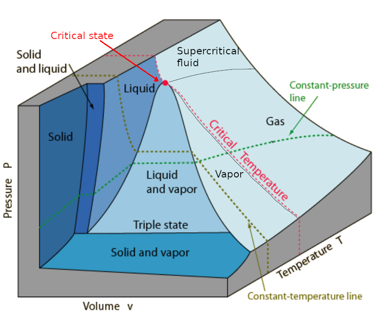
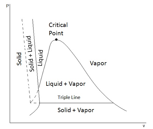
Thermodynamics A binary two phase system has two degrees of freedom. at a given t and p, each phase must have a fixed composition. we can calculate the liquid composition by rearranging eq. 13.2.4: xa = p − p ∗ b p ∗ a − p ∗ b the gas composition is then given by ya = pa p = xap ∗ a p = (p − p ∗ b p ∗ a − p ∗ b)p ∗ a p. A phase diagram in physical chemistry, engineering, mineralogy, and materials science is a type of chart used to show conditions (pressure, temperature, etc.) at which thermodynamically distinct phases (such as solid, liquid or gaseous states) occur and coexist at equilibrium. This fully revised and updated edition covers the fundamentals of thermodynamics, with a view to modern computer applications. the theoretical basis of chemical equilibria and chemical changes is covered with an emphasis on the properties of phase diagrams. starting with the basic principles, discussion moves to systems involving multiple phases. 2.3.2 t v and p v diagrams. in many thermodynamic cycles, a working fluid experiences phase changes between liquid and vapour in the subcritical zone, such as water in a steam power plant and r134a in a vapour compression refrigeration system. the liquid vapour phase change can be illustrated in the and diagrams, as shown in figures 2.3.4 and 2.

Thermodynamics Phase Diagrams This fully revised and updated edition covers the fundamentals of thermodynamics, with a view to modern computer applications. the theoretical basis of chemical equilibria and chemical changes is covered with an emphasis on the properties of phase diagrams. starting with the basic principles, discussion moves to systems involving multiple phases. 2.3.2 t v and p v diagrams. in many thermodynamic cycles, a working fluid experiences phase changes between liquid and vapour in the subcritical zone, such as water in a steam power plant and r134a in a vapour compression refrigeration system. the liquid vapour phase change can be illustrated in the and diagrams, as shown in figures 2.3.4 and 2. A typical phase diagram of a \(p\) \(v\) \(t\) system is shown in the fig. (a). the solid lines delineate boundaries between distinct thermodynamic phases. these lines are called coexistence curves. along these curves, we can have coexistence of two phases, and the thermodynamic potentials are singular. Phase diagram is a graphical representation of the physical states of a substance under different conditions of temperature and pressure. a typical phase diagram has pressure on the y axis and temperature on the x axis. as we cross the lines or curves on the phase diagram, a phase change occurs. in addition, two states of the substance coexist.

Comments are closed.