Plc Program To Implement Various Logic Gates Sanfound Vrogue Co

Plc Program To Implement Various Logic Gates Sanfound Vrogue Co Here is plc program to implement various logic gates, along with program explanation and run time test cases. and. by connecting normally open xic contacts in series, and gate can be implemented. when both inputs are set to 1, then and then only output goes high. or. by connecting normally open xic contacts in parallel, or gate can be. Here is the listing of plc programming examples for different categories viz. digital logic, home and industrial automations. 1. plc programs on digital logic. this section of plc programming examples cover various digital logics likes logic gates, boolean functions and combinational logic circuits. it also contains plc programs on converters.

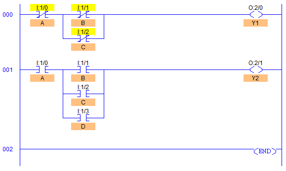
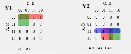
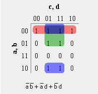
Plc Program To Implement Various Logic Gates Sanfound Vrogue Co Problem description. the input to combinations logic circuit is a 4 bit binary number. design the logic circuit with two outputs (y1, y2) for the following conditions. also develop plc program in ladder logic for the same. y1=1 if the input binary number is 5 or less than 5. y2=1 if the input binary number is 9 or more than 9. 1. 1. and gate in plc programming: using ladder diagram programming, we are connecting two switches (i1 and i2) as input and coil lamp (q1) as output. in the case of both switches (i1 and i2) are closed, the lamp (q1) will glow. in another case, if any of the switches (i1 or i2) are open then lamp (q1) will not glow. In this ladder logic example, there are two inputs. “start button” or plc input i0.0. “stop button” or plc input i0.1. the start button will activate the relay, or ladder logic relay m10.0. when the start button is released, the relay will still be activated, because of the latch in ladder rung 2. 1. explanation: when both input a and input b are 1, the output is 1. for all other combinations of inputs, the output is 0. ladder logic diagram: in the ladder logic diagram, the series connection of two contacts (a and b) represents the and gate. both contacts must be closed (true) for the output coil to be energized.

Plc Program To Implement Various Logic Gates Sanfound Vrogue Co In this ladder logic example, there are two inputs. “start button” or plc input i0.0. “stop button” or plc input i0.1. the start button will activate the relay, or ladder logic relay m10.0. when the start button is released, the relay will still be activated, because of the latch in ladder rung 2. 1. explanation: when both input a and input b are 1, the output is 1. for all other combinations of inputs, the output is 0. ladder logic diagram: in the ladder logic diagram, the series connection of two contacts (a and b) represents the and gate. both contacts must be closed (true) for the output coil to be energized. Implementation of logic gates using plc program. 1. and gate. and logic gate is the basic multiplication logic gate. the output will turn on only if all the inputs will be on. and gate: y = a * b. the below figure shows the plc ladder logic of and gate, which shows the output coil turns “on” when both the input will be on. A plc or programmable logic controller is a special type of digital computer without a monitor and keyboard. this is basically used in industrial automation such as manufacturing, automotive, food and beverage, chemical processing, and more to automate systems. this tiny computer receives data through input and sends operating instructions as.

Plc Program To Implement Various Logic Gates Sanfound Vrogue Co Implementation of logic gates using plc program. 1. and gate. and logic gate is the basic multiplication logic gate. the output will turn on only if all the inputs will be on. and gate: y = a * b. the below figure shows the plc ladder logic of and gate, which shows the output coil turns “on” when both the input will be on. A plc or programmable logic controller is a special type of digital computer without a monitor and keyboard. this is basically used in industrial automation such as manufacturing, automotive, food and beverage, chemical processing, and more to automate systems. this tiny computer receives data through input and sends operating instructions as.

Plc Program To Implement Various Logic Gates Sanfound Vrogue Co

Comments are closed.