Reference Planes In Technical Drawings

Ppt Drafting With Auxiliary Views Powerpoint Presentation Free X 673 64 1f supersedes gsfc x 673 64 1e july 1991 engineering drawing standards manual mechanical engineering branch goddard space flight center. The representation of the object in figure 2 is called an isometric drawing. this is one of a family of three dimensional views called pictorial drawings. in an isometric drawing, the object’s vertical lines are drawn vertically, and the horizontal lines in the width and depth planes are shown at 30 degrees to the horizontal.

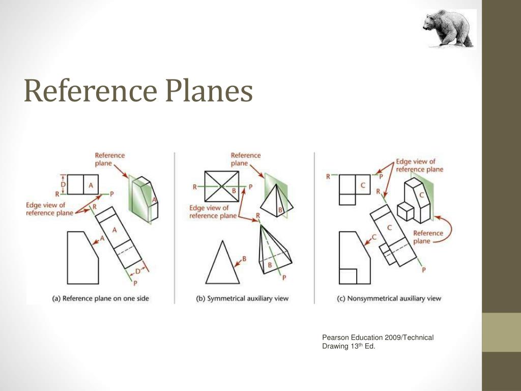
Engineering Drawing Line Inclined To Both The Reference Planes Youtube Projection: • the figure or view formed by joining, in. correct sequence, the points at which. these lines meet the plane is called the. projection of the object. the lines or rays drawn from the object to. the plane are called projectors. the transparent plane on which the. projections are drawn is known as plane of. Planes circles arcs 4.1 manually bisecting a line or circular arc 4.2 drawing tangents to two circles 4.3 drawing an arc tangent to a line or arc and through a point 4.4 bisecting an angle 4.5 drawing a line through a point and parallel to a line 4.6 drawing a triangle with sides given 4.7 drawing a right triangle with hypotenuse and one side given. Chapter nine.auxiliary views. objectives. after studying the material in this chapter, you should be able to: 1. create an auxiliary view from orthographic views. 2. draw folding lines or reference plane lines between any two adjacent views. 3. construct depth, height, or width auxiliary views. Home archives archival collections technical and scale drawings. our archives is the repository for more than two million aircraft and spacecraft technical and scale drawings, donated over the decades by manufacturers, the armed services, and by individual illustrators. most drawings are available for reproduction.

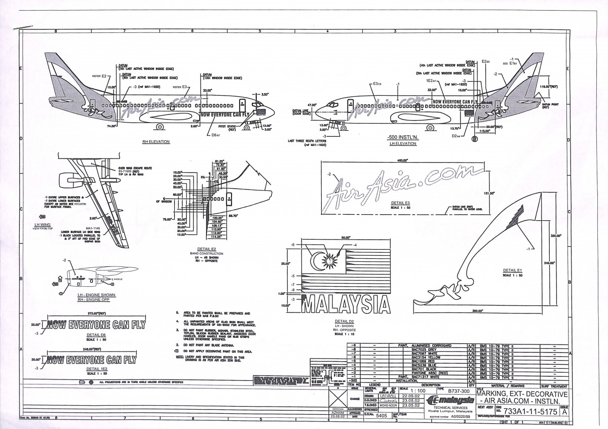
Aircraft Technical Drawings вђ Airasia Museum Chapter nine.auxiliary views. objectives. after studying the material in this chapter, you should be able to: 1. create an auxiliary view from orthographic views. 2. draw folding lines or reference plane lines between any two adjacent views. 3. construct depth, height, or width auxiliary views. Home archives archival collections technical and scale drawings. our archives is the repository for more than two million aircraft and spacecraft technical and scale drawings, donated over the decades by manufacturers, the armed services, and by individual illustrators. most drawings are available for reproduction. Datums are theoretically perfect but imaginary planes, axises, and points used for creating reference frame in a drawing. this reference frame is used for dimensioning for the drawing and model creation. datums are established from the datum features. if you have a point datum, then only one datum is sufficient to constrain the model. In a standard set of architectural plans on a small residential project, the elevations will most likely be a set of drawings from the main facades of the building. for example, front, back and two sides – or north, south, east and west. the sections would most likely be two or more sections cut at 90 degrees of one another to give.

What Is Reference Plane Horizontal And Vertical Plane Youtube Datums are theoretically perfect but imaginary planes, axises, and points used for creating reference frame in a drawing. this reference frame is used for dimensioning for the drawing and model creation. datums are established from the datum features. if you have a point datum, then only one datum is sufficient to constrain the model. In a standard set of architectural plans on a small residential project, the elevations will most likely be a set of drawings from the main facades of the building. for example, front, back and two sides – or north, south, east and west. the sections would most likely be two or more sections cut at 90 degrees of one another to give.

Technical Drawing Plane And Solid Geometry Ordinary Level Questions

Comments are closed.