Reversal Of A Three Phase Motor

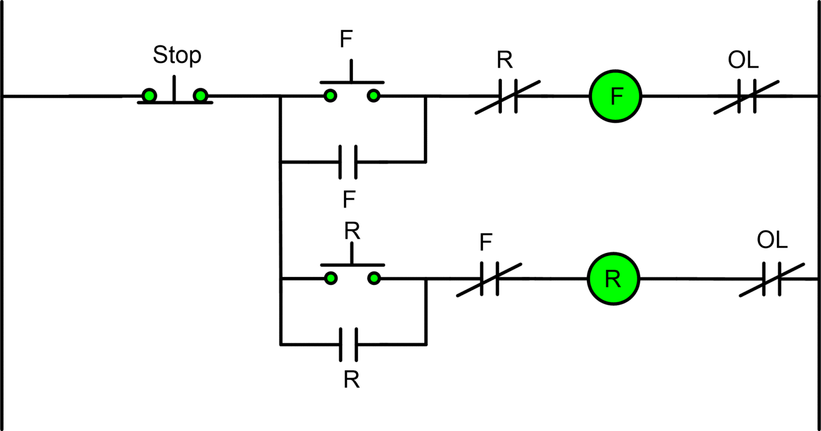
Static Reversing The Three Phase Induction Motor The contactor should have three main terminals for the three phase power supply (l1, l2 & l3) and three auxiliary contacts for control circuits. install a relay with two sets of contacts, one for forward operation and the other for reverse operation. connect the relay to the control circuit of the contactor. connect the three phase power supply. The reversing circuit of a 3 phase motor uses a 3 position switch to control 2 contactors (the figure below uses the 2 position switch symbol instead of the 3 position switch). one contactor is connected to the motor to run forward, the other when closed will swap two of the three wires of the motor. how to reverse a 3 phase motor using switch.

Reversing Three Phase Induction Motors Electrical A2z 🔧🚀 how to reverse the direction of a three phase motor: swapping two lines! ⚡️🔄🔧 in this clip from our stop forward reverse circuit series, we delve into. In this video, we'll be covering the basics of motor control circuits for forward and reverse operation of three phase motors. we'll discuss the components o. In this video, we'll show you how to use a reverse switch to control the rotation direction of a 3 phase induction motor and explain why it's more advisible. The phases have a phase shift of 120 degress called electrical phase angle, meanwhile the windings on the motor are also shifted by 120 deg mechanical angle. in a such way, when the current passes trough windings the rotating magnetic field is formed, which is the sum of all three vectors.

Diagram Of 3 Phase Reversing Motor Control With 24 Vdc Control Voltage In this video, we'll show you how to use a reverse switch to control the rotation direction of a 3 phase induction motor and explain why it's more advisible. The phases have a phase shift of 120 degress called electrical phase angle, meanwhile the windings on the motor are also shifted by 120 deg mechanical angle. in a such way, when the current passes trough windings the rotating magnetic field is formed, which is the sum of all three vectors. This comprehensive article guides readers through the process of changing the direction of rotation in a three phase electric motor by swapping two of the three motor leads. at ets, we always emphasize safety as a top priority. as such, we outline crucial steps, such as disconnecting power, identifying motor leads, and noting the initial rotation. Power wiring: connect the 415v ac three phase power supply from the 3 p mccb to the vfd’s l1, l2, and l3 terminals. now connect the three phase motor to the vfd’s output terminals of t1, t2 and t3. make sure the correct phases are matched and in sequence. if not sure, follow the manufacturer’s guidelines for proper wire sizing and.

Comments are closed.