Rsk2 Diagram Evap Cooler Switch

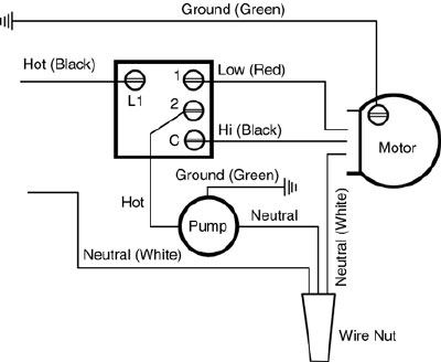
Evaporative Swamp Cooler Wall Switches K S Sales And Supply This switch is recommended for 120 volt applications only. this diagram is a basic schematic and is not intended to represent all methods of installation because of various cord, plug, and pump configurations. see evaporative cooler installation instructions and motor and pump instructions for proper motor and pump wiring. The white wires or neutral connect to the common junction point on the water pump and the white connection point on the switch. the green wire functions as the ground and connect to the ground points and is held in place by a nut. the green is also connection to the switch ground. on the switch side, the black connects to the l1 terminal.

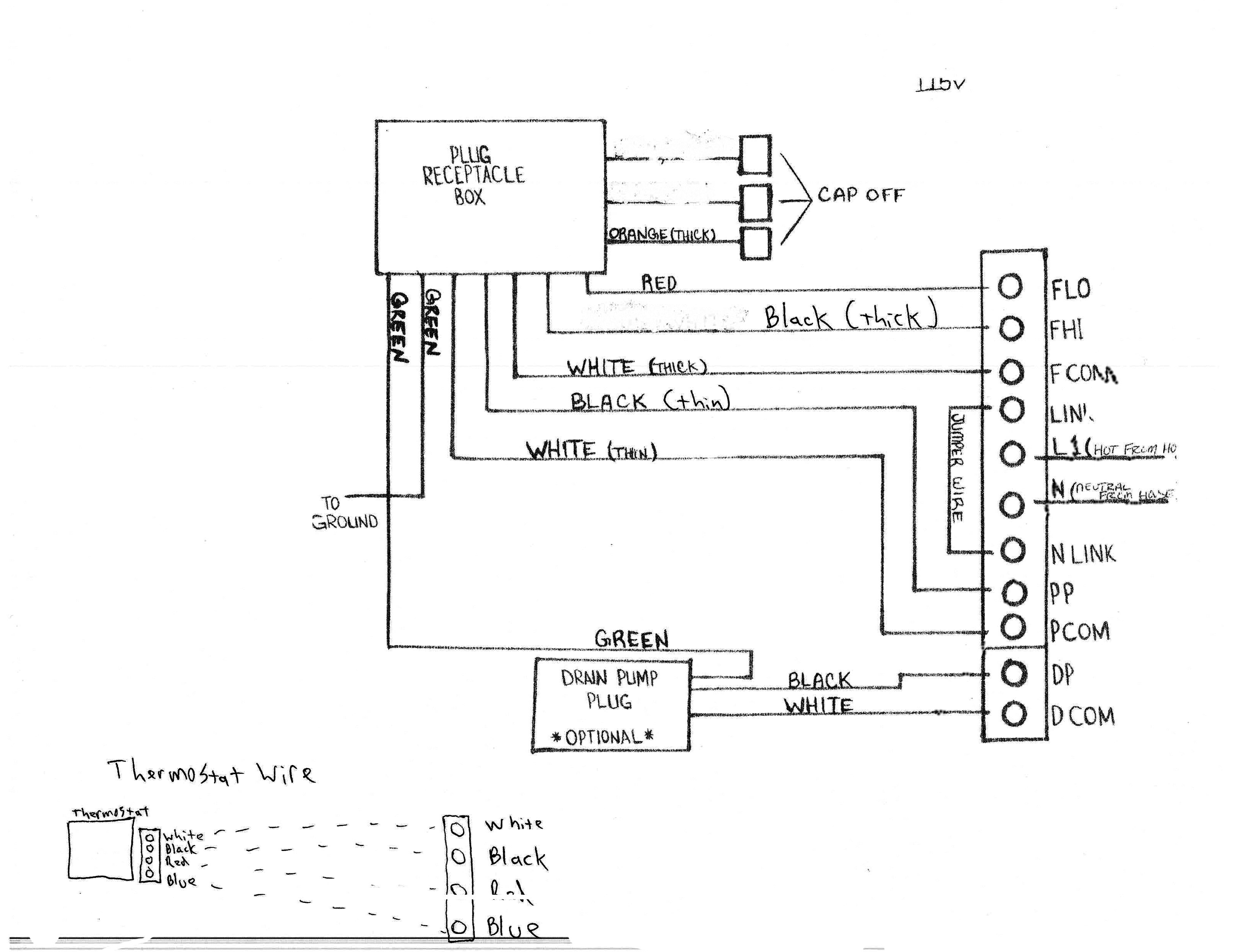
2 Speed Wall Switch Rsk2 2x4 Evaporative Cooler Switch Dial An evaporative cooler switch wiring diagram is a schematic that shows the various connections and components of a switch used in an evaporative cooler. this diagram helps electricians and technicians understand how the switch should be wired and connected to the cooler’s motor and power source. evaporative coolers, also known as swamp coolers. 6 position white plastic plate rated for ⅓ to 1 hp motors. for single & two speed motors. includes wall switch, mounting screws & wiring diagram. ul recognized component rotary switches. part # 7112 – card. part # 71105 – display carton & bag. part # 7110 – bag (10) part # 7110 7112 category: switches. description. Id500c12 3 4 hp 2 speed 115 volts 1 phase aerocool commercial blower section ws100a rigid media cooler 12 inch wet section (115 volt pump & float) call us today for more info. commercial coolers. Step 3. take the black wire from the motor and connect it to the high speed terminal of the switch. the remaining terminal on the switch supplies power to the evaporative cooler pump. connect the black wire of the pump to this terminal. connect all of the remaining white neutral wires and bind them together with a plastic twist cap.

Switch Wiring Diagram For Evap Cooler Id500c12 3 4 hp 2 speed 115 volts 1 phase aerocool commercial blower section ws100a rigid media cooler 12 inch wet section (115 volt pump & float) call us today for more info. commercial coolers. Step 3. take the black wire from the motor and connect it to the high speed terminal of the switch. the remaining terminal on the switch supplies power to the evaporative cooler pump. connect the black wire of the pump to this terminal. connect all of the remaining white neutral wires and bind them together with a plastic twist cap. The cooler before installing or performing any maintenance. 4. your cooler will run on either 120v or 240v a.c., single phase, 60 hz (cycle) current. 5. motor and pump have a grounded, molded plug and an automatic thermal overload switch which will shut motor off when it overheats. the motor will restart automatically when it cools down. Connect the switch: if your swamp cooler has a 2 speed switch, connect the high speed wire from the motor to the terminal marked “hi” on the switch, and the low speed wire to the terminal marked “lo.”. ensure that the switch is properly wired and tightened. secure the ground wire: attach the ground wire from the motor to the grounding.

Evaporative Cooler Switch Wiring Diagram The cooler before installing or performing any maintenance. 4. your cooler will run on either 120v or 240v a.c., single phase, 60 hz (cycle) current. 5. motor and pump have a grounded, molded plug and an automatic thermal overload switch which will shut motor off when it overheats. the motor will restart automatically when it cools down. Connect the switch: if your swamp cooler has a 2 speed switch, connect the high speed wire from the motor to the terminal marked “hi” on the switch, and the low speed wire to the terminal marked “lo.”. ensure that the switch is properly wired and tightened. secure the ground wire: attach the ground wire from the motor to the grounding.

Evaporative Cooler Switch Wiring Diagram

Comments are closed.