Running Led Chaser Circuit With Cd4017 Led Sequence Light Circuit

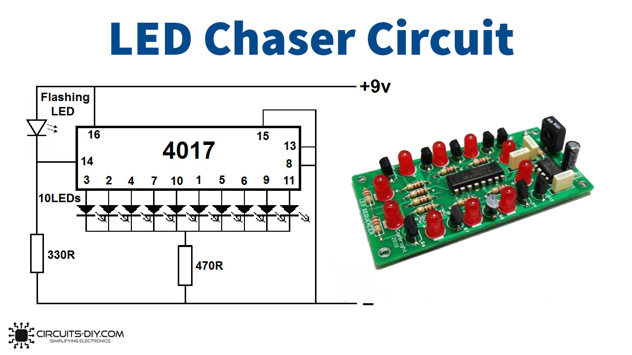
Running Led Chaser Circuit With Cd4017 Led Sequence Light Circuit In this tutorial, we are going to demonstrate a led sequencer chaser using ne555 & cd4017. the purpose of this circuit is to turn the leds on one by one. cd4017 is a cmos counter ic, it gives 10 outputs according to the clock pulse it receives from the clock input (pin 14). ne 555 is a timer ic which is a very versatile ic widely used in. Simple 12 led light sequencer circuit. here is a 12 led light sequencer circuit using cd4017 and ne555 as main components. we modified it from the led chaser circuit. the difference is that the light starts from two ends and then meets in the middle, and both go back to the start, and the process is repeated.

Led Chaser Circuit Using Cd4017 And 555 The ic 4017 is decade counter with 10 decoded outputs ic ic. circuit diagram of 2 way 12 led running lights using cd4017 and ne555. which its output glowing will slide down each position, by begin from output at 1 is pin 3, 2, 4, 7, 10, 1, 5, 6, 9 and 11 in sequence. when it to pin 11 the output light will back to pin 3 and continue to glow in. Working of led chaser circuit based on 555 timer & cd4017. once the circuit is complete, apply power to see the leds chasing one another in sequence. the speed of the chasing effect can be adjusted by changing the values of the resistors and capacitor in the 555 timer ic circuit. for example, you can try different resistor and capacitor values. Step 2: circuit diagram & other details. construct the circuit as shown in the circuit diagram. for making the led chaser you require 555 timer & 4017 counter. the 555 timer is used to produce the clock pluse for the 4017. the 4017 is constructed in a astable configuration. when the clock pulse produced by the 555 timer is fed to the 4017, it. Hi this video is to show you how to make a simple running led chaser. circuit running led chaser circuit with cd4017 || led sequence light circuit | using.

24 Channel Led Chaser Circuit Diagram Step 2: circuit diagram & other details. construct the circuit as shown in the circuit diagram. for making the led chaser you require 555 timer & 4017 counter. the 555 timer is used to produce the clock pluse for the 4017. the 4017 is constructed in a astable configuration. when the clock pulse produced by the 555 timer is fed to the 4017, it. Hi this video is to show you how to make a simple running led chaser. circuit running led chaser circuit with cd4017 || led sequence light circuit | using. In an led chaser circuit, the 555 timer is configured as an astable oscillator, which means that it will generate a continuous stream of pulses. the frequency of the pulses can be adjusted by changing the values of the resistors and capacitors that are connected to the timer ic. the pulses generated by the 555 timer are then used to control a. March 2, 2017. this is a simple cd4017 based led light using ne555 timer for clock generation. we have used only two cd4017 ics to construct the project in 9×9 matrix format. the circuit is useful for applications like running light systems in halls, decorations, dance programmes, counting and so on. fig. 1 shows the author’s prototype.

Led Chaser Circuit Using Cd4017 And 555 In an led chaser circuit, the 555 timer is configured as an astable oscillator, which means that it will generate a continuous stream of pulses. the frequency of the pulses can be adjusted by changing the values of the resistors and capacitors that are connected to the timer ic. the pulses generated by the 555 timer are then used to control a. March 2, 2017. this is a simple cd4017 based led light using ne555 timer for clock generation. we have used only two cd4017 ics to construct the project in 9×9 matrix format. the circuit is useful for applications like running light systems in halls, decorations, dance programmes, counting and so on. fig. 1 shows the author’s prototype.

Led Sequencer Chaser Using Ne555 Cd4017 вђ Artofit

Comments are closed.