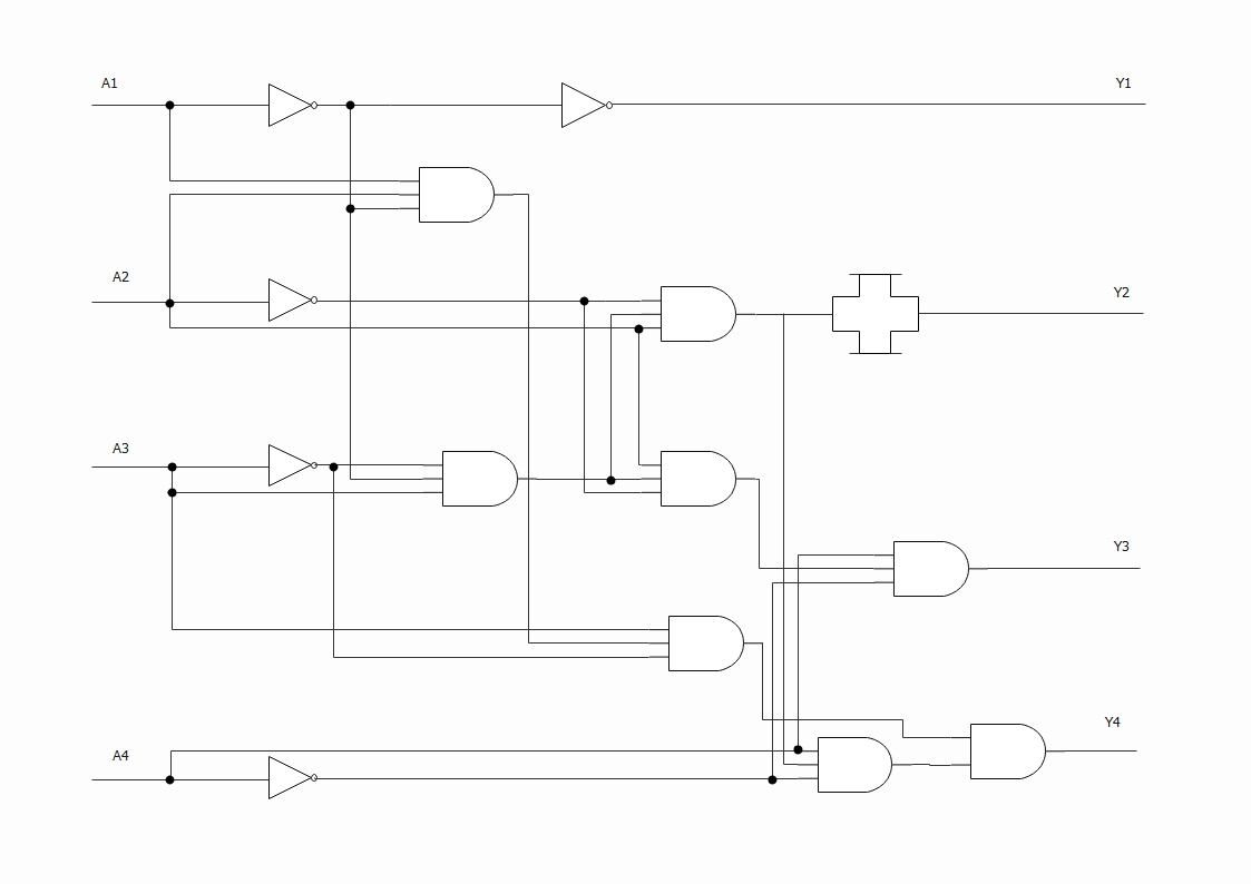
Schematic Diagram 5

Draw Schematic Diagram 5 Light Bulbs Connected In Parallel Controlled An electrical schematic is a diagram that shows how all of the wires and components in an electronic circuit are connected. they’re like a map for building or troubleshooting circuits, and can tell you almost everything you need to know to understand how a circuit works. the ability to read electrical schematics is a really useful skill to have. Understanding how to read and follow schematics is an important skill for any electronics engineer. this tutorial should turn you into a fully literate schematic reader! we'll go over all of the fundamental schematic symbols: then we'll talk about how those symbols are connected on schematics to create a model of a circuit. we'll also go over a.

Schematic Diagram A Complete Tutorial With Free Examples Edrawmax But reading and interpreting schematic diagrams is no easy task – each line, symbol, and color is carefully selected to represent something specific. fortunately, with a bit of practice, it’s possible to master the art of reading and interpreting schematic diagrams. the first key to success is understanding the symbols used in the diagram. An example can be taken of the pcb, and an electronics expert uses the schematic diagram to make the base of the pcb used to make chips and microcontrollers. since these are simple and use pictures to depict components, it can be used by simple handymen as well. even simple homeowners can identify the components. A schematic diagram is a visual representation of a system or process, using symbols, lines, and arrows to show the connections and flow of the various components or elements involved. it is a way to illustrate complex ideas or concepts in a concise and organized manner. using a schematic diagram, engineers, technicians, and other professionals. Published on january 29, 2019. a schematic is defined as a picture that shows something in a simple way, using symbols. a schematic diagram is a picture that represents the components of a process, device, or other object using abstract, often standardized symbols and lines. schematic diagrams only depict the significant components of a system.

Comments are closed.