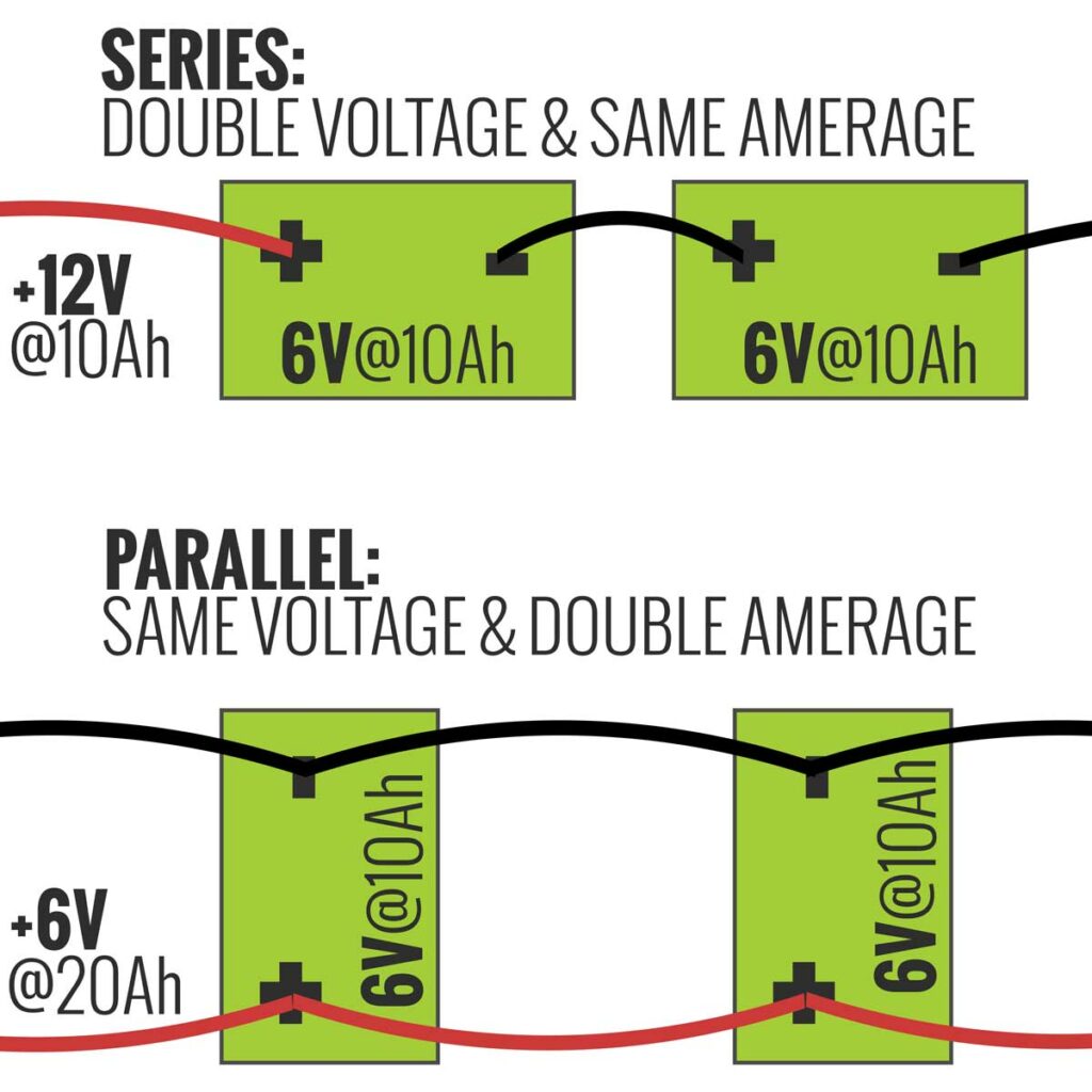
Series And Parallel Wires

Parallel And Series Wiring It is easier to wire a series circuit than a parallel circuit. the incoming cable is attached directly to the device (like a receptacle), and the outgoing cable is also directly attached. a parallel circuit requires you to pigtail wires and to add wire nuts. so, electrical project costs are slightly less when wiring a series circuit. A series circuit’s defining characteristic is that all components in a series circuit have the same current flowing through them. there is only one path for the current to flow. in the circuit from figure 2, the current (i) flows clockwise to complete a full loop from the positive battery terminal back to the negative terminal and then.

Wiring In Parallel And Series Series and parallel circuits. a series circuit with a voltage source (such as a battery, or in this case a cell) and three resistance units. two terminal components and electrical networks can be connected in series or parallel. the resulting electrical network will have two terminals, and itself can participate in a series or parallel topology. When deciding between series and parallel wiring, it is crucial to consider the specific requirements of your electrical system. if reliability and redundancy are important, parallel wiring may be the better choice. however, if simplicity and cost effectiveness are paramount, series wiring might be the way to go. The circuit carries current only if all switches are closed (on). but in a parallel circuit, two or more switches make a logical or gate. current flows as long as any one of the switches is closed. references. series and parallel circuits ; introduction to circuits: parallel and series circuits. Series wiring is commonly used when the components need to share current evenly or when the total voltage needs to be divided among the components. parallel wiring: in parallel wiring, the components are connected side by side, providing multiple pathways for the current to flow. each component in a parallel circuit has the same voltage across.

Parallel And Series Circuit Wiring Diagram Ed Electrical Tech Youtube The circuit carries current only if all switches are closed (on). but in a parallel circuit, two or more switches make a logical or gate. current flows as long as any one of the switches is closed. references. series and parallel circuits ; introduction to circuits: parallel and series circuits. Series wiring is commonly used when the components need to share current evenly or when the total voltage needs to be divided among the components. parallel wiring: in parallel wiring, the components are connected side by side, providing multiple pathways for the current to flow. each component in a parallel circuit has the same voltage across. Wiring in series and parallel diagram is an important concept in electrical engineering and is used to connect multiple components or devices in a circuit. understanding this concept is essential for designing and analyzing complex electrical systems. when components are wired in series, they are connected end to end, creating a single path for. Tip #3: power ratings in series parallel. this sort of series and parallel combination of resistors works for power ratings, too. let’s say that we need a 100Ω resistor rated for 2 watts (w), but all we’ve got is a bunch of 1kΩ quarter watt (¼w) resistors (and it’s 3am, all the mountain dew is gone, and the coffee’s cold).

Series And Parallel Wiring Diagram Homemadeist Wiring in series and parallel diagram is an important concept in electrical engineering and is used to connect multiple components or devices in a circuit. understanding this concept is essential for designing and analyzing complex electrical systems. when components are wired in series, they are connected end to end, creating a single path for. Tip #3: power ratings in series parallel. this sort of series and parallel combination of resistors works for power ratings, too. let’s say that we need a 100Ω resistor rated for 2 watts (w), but all we’ve got is a bunch of 1kΩ quarter watt (¼w) resistors (and it’s 3am, all the mountain dew is gone, and the coffee’s cold).

Wiring In Parallel And Series At Travis Daughtry Blog

Comments are closed.